Marc Stoiber recently sat down with Jim Nelson - Senior Marketing Manager at BC Hydro, and extracted Jim's list of seven psychological barriers to the general public accepting and embracing 'green' (Full interview).
But I believe there may be another even bigger barrier, that Jim has missed, and that is ignorance. I do not mean this in a negative way, but a true definition of the word way. You see, I consider myself fairly well informed on many energy efficiency issues and I definitely want to do the 'right' thing, even if it costs me a little extra in the short term.
But what is the 'right' thing?
I presently do not have enough knowledge to make that decision and I believe that many people would be in a similar or even worse situation. I have spent a LOT of time researching my upcoming build. I have literally spent hundreds if not thousands of hours over several years researching the best practices of building envelopes, HVAC, electrical efficiency, etc. But in many ways, I am no closer now to being able to make the 'right' decisions than when I started. There is so much information available these days thanks to the internet and search engines like Google. Answers are literally a few clicks away, but unfortunately much of these answers are conflicting depending on the bias or knowledge of the presenter. You are often unable to determine the best course of action.
This has often left me felling frustrated and can paralyze you from moving forward. An example is needed:
Over the last few days there has been a discussion on Linked-In asking about the sanity of using electric resistance baseboard heaters (Full Discussion - Building Science Group: Have we lost our minds when we use resistance heating in low load buildings?) I have been actively participating in this conversation because I though I could provide knowledgeable responses. But in the end, my assumptions were challenged leaving me wondering where I stood and feeling quite ignorant on the subject.
The basic premise I first had was based on the fact that I live in a region blessed with abundant clean energy, that being Hydro Electric. Currently, 90% of our Province's power comes from Hydro Electric generation with the balance being made up with Natural Gas fired Thermal (7.5%) and the rest is purchased energy (much of it from Alberta's coal generation with a smattering of renewable like wind). My logic was that I should utilize this 'green' energy in my upcoming build in order to reduce my carbon contribution to the planet. I would look at an air source heat pump ASHP (utilizes electricity to harvest free 'heat' from the air outside your home much in the same way as your refrigerator works to evacuate heat from its interior - just in reverse). I would use the heated refrigerant created by the ASHP to heat water (through the use of a heat exchanger) that would then be circulated through radiant panels I would place in my walls and ceilings (I will discuss why I will not do radiant floors in a future blog). In the summer time, I would reverse the heat pump and created chilled water that I could then use to help cool the home.
Many models of ASHP are available, but efficiencies as high as 4+ are available (meaning for every unit of electricity used, there will be 4 units of heat available). This sounds pretty good, doesn't it. But we are not done yet, we also have to take into account the source losses for the energy used and reduce our efficiency accordingly.
In a conversation I had with Dr. John Straube of Building Science Canada last winter, he suggested that an appropriate way to look at electricity generation may be to look at all of the generation sources feeding your particular electrical interconnection. I am part of the Western Electric Coordinating Council (WECC) interconnect which does have a lot of hydro electric generation, but is also supplemented by dirtier generation sources like coal. He suggested a source energy factor of 1.5 to 1.7 may be appropriate (for every kWh consumed at site, 1.5 to 1.7 kWh must be generated. The .5 to .7 lost kWh's represents transmission losses and generation inefficiencies). So a ASHP efficiency of 4 now drops to 2.35 - 2.67 when taking into account the source energy factor. Not as good but still at least 235% efficient.
What are the alternatives? For me, the logical alternative would be a high-efficiency-modulating-condensing-natural gas fired boiler. These type of units can have a site energy efficiency of 95%+ which translates into a source efficiency around 90% when adding in a 1.05% source energy factor (yes there are also 'transmission' losses - venting and pumping - in gas pipelines that account for most of the 5% loss). This is starting to look a lot less attractive. We have 90% efficient gas compared to 235%+ efficient electricity, and this formed the basis of my preliminary decision to not even re-connect the gas line up to my upcoming build.
Now the original Linked-in conversation was considering the use of electric resistance baseboard heaters. These are considered to have a 100% site efficiency which would translate into a 66% down to 59% source efficiency when taking into account the source energy factor of my region. This is poor in comparison with even the Natural Gas fired boiler efficiency. I would never consider such a heating source UNLESS the heating load was so low, due to the envelope efficiency, that electric resistance baseboards or radiant panels were the only heat source that could ramp down low enough to not overheat the dwelling. This can often be the case in dwellings that have extreme levels of insulation like those certified in the PassiveHaus program. These homes, by virtue of their certification, must have heating loads not exceeding 10W per square meter of living space. Unless the dwelling is quite large, this low of a load is often exceeded even by the smallest equipment currently available on the marketplace. Unfortunately, electric resistance baseboards are common in my region for some single family houses and abundant in multi-family housing.
On the surface, the decision looks easy - choose the 235% minimum efficient ASHP and that was were I stood a day ago. But I was then challenged by individuals in the discussion to visualize a larger picture. As mentioned I live in BC which has an abundance of hydro. My interconnect also has a high ratio of Hydro arguably giving it a source energy factor around 1.5 to 1.7. The rest of the USA in comparison is dirty, to just plain filthy, due to its heavy dependence on coal fired power plants. The average source energy factor for the USA is around 3.3 meaning for every unit of electric energy used in the home, 3.3 units of energy have to be created and added to the grid. This would bring our ASHP example down to a efficiency of 1.2 or 120%. Still better than gas but a lot worse than the average for my region. An electric baseboard on average in the USA would only have a efficiency of 30% when the source factor is taken into account - clearly a poor choice!
On the surface, no regions should use electric baseboards (unless the loads are VERY low) and in all regions, an efficient ASHP would be a better choice than even the most efficient gas boiler or forced air furnace. Again, the decision seems clear - right??
But what happens when a person in a region with 'green' hydro energy decides to use a gas fired heating system to reduce their electrical usage to allow more of that 'green' electricity to feed into the grid, and by doing so, hope to reduce the ratio of filthy coal power?
Does anyone benefit? Will the extra kWh's made available offset coal production or will the power just be consumed by increased demand of a non-energy conserving nation? How does one predict the actions of a consumer? How does one measure the result of such a decision? Should one use a 'green' electricity themselves, or use a dirtier energy so that they can pass on their clean power to users that only have filthy electricity available?
What is the right answer??? This is just one example of how difficult the right answer may be to obtain. An ignorance of the needed facts to make the right decision can paralyze a person from making any decision, which in turn could often lead to the adoption of the status quo (one of the barriers mentioned by Jim Nelson).
Now of course, I do not have this as an option. I must put some form of heating system into my planed build. To this end, I would appreciate input from those with relevant knowledge, that could help provide the information I need to make this decision.
Sunday, 30 December 2012
Friday, 28 December 2012
Scotland Recycling and Vegetable Production
Well, it seems I may need to eat some crow and post some
updates to my comments regarding recycling and food production in Scotland.
I was contacted by a work colleague from a company I used to
work at, who is a proud Scott and had read my entry. He was not in agreement regarding my comments
on both the lack of recycling in Scotland and the lack of fresh-locally-grown vegetables. This interaction encouraged me to do a little
research.
I have contacted each of the establishments I stayed at and
have asked for the status of any recycling programs they may have. I will post the replies as received. In the meantime, I did some Google searching regarding recycling in Scotland and found some
great info. Programs do exist, but they seem to be limited in regions served and
frequency.
A great site to start at is http://www.recycleforscotland.com/recycle.asp. I was unable to get a match for any of the locations
we stayed at (may not have picked the right regions), but it seems the program
is centred around major urban regions only. For many of the listed areas, there does seem
to be great service including a ‘Blue Box’ program similar to our own. The site claims 93% of households in Scotland
have access to kerbside recycling facilities and the rest have “Recycling
Centres & Points” to take your recycled products to.
Another great site was http://www.zerowastescotland.org.uk/
which seems to be more of an educational and support organization and not into
the day to day activities of recycling.
It appears that through education and lobbying, this organization is
creating a greater awareness and need to recycle and reduce. It had great information on the need to
recycle and how recycling impacts our planet and material stream.
I then Goggled “Recycling Centres & Points” for each of
the locations we stayed at and found that some had a Centre close enough to be practical.
For instance, The Isle of Mull had a
centre in the very town we stayed in: Tobermory. Dornie had a point at their town centre. Some spots like the one in Balquhidder, did
not appear to have any reasonable options.
So I am a bit perplexed, both my wife and I are very used to
recycling at home and out and about in our daily lives. Even our ‘remote’ vacations in Tofino involve
separating all recycling into provided bins and taking the ‘loot’ with us to
drop off at the local centre (about 20 minutes away from Tofino near Long Beach)
when we are heading back to the Mainland.
So we are very used to looking for the bins, yet in all of the places we
stayed at, there was no obvious facility to separate out the recyclables from
the main garbage stream. I would imagine
that the Blue Box programs are fairly successful where available, after all, how much effort is
involved with throwing goods into a blue box compared to a garbage can. But if a resident has to store up the
recycling materials and bring them to a location that may be 30 minutes or more away, I
can understand (unfortunately) the hesitance many would have in participating
in such a program.
Does this mean that even though the facilities may be
available, they are not used by a large percentage of the population? Do only ‘urban’ residents participate? I do not have the answers. If you are reading this blog and live in
Scotland, I would love to hear from you.
As a side note – I also checked on Chicago and confirmed it
does NOT have an active recycle program.
The cost of the blue box program was turned down years ago and has to
date never been re-initiated.
So, now to the topic of Scottish produce. Again, I turned to Google. The first site I visited (http://www.scotland.org), advised that Scotland
grows 2,400 tonnes of raspberries, 4,600 tonnes of strawberries, and over a million tonnes of potatoes per year.
900 million eggs are produced annually, 1,300 million litres of milk and there
are more than two dozen cheese-makers across Scotland, ranging from the
industrial cheddar creameries to much smaller-scale cheese producers (I wonder if this is a misprint as we probably have 2 dozen cheese producers in our local Gulf Islands). The site went on to state "However,
beef is now the single most important sector of Scottish agriculture, worth
around £400 million a year: more than fruit, dairy and poultry combined!" It
also stated "The jewel in Scotland’s crown is her fish with nearly 200
shellfish farming companies. Salmon farming is the most important economic
development in the Highlands and Islands over the past 30 years, and the retail
sales value of Scottish salmon is around £300 million per annum. Scotland is
the world’s third largest producer of Atlantic salmon and enjoys a reputation
for quality fresh and added-value products such as smoked salmon."
http://www.nfus.org.uk
indicated that most of the soft fruit farming is in Tayside, Angus, and similar
fertile areas near Dundee (an area we did not visit but is near where my colleague grew up and forms the basis for his points of view).
I then visited http://forsythfreshproduce.co.uk/index/fresh-produce-seasonal-report
and read where all the salad ingredients come from basically the UK and
Holland. Most of the vegetables were
UK/France/Spain/Holland. These results
are for June which arguably is some of the best growing weather for crops like salad greens. This information aligns with the information we
were given by the ‘locals’ on our trip. “Veggies and Salad greens are not grown
locally and imports are often expensive”.
Additional sites indicated limited cauliflower, broccoli, and leek
production was also present in Scotland. It was
interesting to see that the Beef industry was so big in Scotland. We saw our first cow when leaving Scotland
near the Inverness airport, up until that time we only saw sheep.
http://eatscotland.visitscotland.com/food-drink/in-season/
was an excellent site to show what is potentially available fresh and local per
season.
So again, I am left a bit perplexed. If the growing conditions support fresh
vegetable production and they are available in the marketplace, Why are they not served
more often?
One of the locations we
stayed at (Monachyle
Mhor) had its own garden, and we did have some lovely cooked greens and
carrots while staying there, but our first real salad did not occur until the
end of our journey at The Old Inn in Gairlock.
Our stays in Edinburgh, Tobermory, Dornie, and Nairn had considerably
less choice for products that grew above the ground and left us wanting
more.
Why don’t more residents have
their own mini-gardens to bolster their vegetable availability? There certainly was the room for them in most
locations we visited. Are there difficulties
I am not aware of? Or is this just a
menu preference of many of the Scottish peoples? If so – why?
Where has the habit of game and root vegetable dominance originated? All topics for someone else’s blog I am
afraid but I would love to hear from any of you that may have some insight.
Our general experience was a starting lack of fresh vegetables being
made available to us during our journey.
This is the experience that initiated the original blog entry. The thought process then evolved into our
society’s general reliance on transporting fruits and vegetables and other
produce clear around the world, regardless of seasons. This is a global phenomenon and certainly is
much worse at my local supermarket than anything I encountered in the UK.
It is I believe not a sustainable
practice. It is one I hope to curb in my
personal life once I finish my upcoming build and would be able to set up
a garden in our back yard. I hope to
provide a majority of our vegetable needs for at least three seasons of the
year. Will I still buy Japanese mandarins
every Christmas, California cucumbers in the winter, and Mexican fruit in the
early spring? Probably, but in the mean
time, I am also trying to find many more local sources of produce that is grown
or raised in BC to limit the energy it takes to get food to my table.
Thursday, 20 December 2012
May I present "The Enclosure"!
Well the days are ticking down and the stress level is rising, but I finally have a finished floor plan and reasonably advanced 3D model I can share with you. These are exciting times!
I have decided to call the project "The Enclosure" (sorry, no one won the $50 prize) to reflect my focus while designing.
I will use this blog and a new website that will launch in the months to come (www.TheEnclosure.ca) to promote what I feel are good decisions that encompass the below 9 guidelines. I also hope to include hourly construction photos during the entire build, live camera feed from two angles, manufacture’s technical information on the products I choose, and most important, real life figures as to cost and performance of the built dwelling, on this new website.
I hope to work with the utilities to provide live monitoring of site used energy and will also approach groups like HPO, BCIT, and the Building Envelope Engineering sector to design laboratory experiments that will provide real feedback, from the site, on the effectiveness and durability of different wall assembly structures.
To that end, I will design a 8ft high x 8ft long ‘opening’ on the north-top-floor-exterior-wall that will allow the installation of multiple ‘plug and play’ wall assemblies with instrumentation. This will allow the recording of wood moisture, relative humidity, temperatures, and heat flux through the various assemblies over time. The results, I hope, will allow calibration of computer models and determination by building officials as to appropriate assemblies to support in code changes for decades to come.
The instrument readings, I hope, would also be made available live on my website. In this way, the dwelling could have a real contribution to the scientific community and would help my goal of creating a legacy instead of a liability.
Now, if you read some of my earlier entries, you will see that this process started for me back in 1981 when I took my first drafting course in high school. Some of the concepts represented in a design I worked on through high school are still incorporated in my modern day design. Items like a low slopped roof, vaulted ceiling above the stairs and bedrooms, 'light wells', a ‘great room’, and a shop in the basement.
Other concepts are much more recent, like optimizing the floor space to be as compact as possible, incorporating SAFERhomes standards, generally following the principles of PassiveHaus, and most importantly - putting the building enclose much higher in the priorities list (with the larger portion of the budget to match).
I believe that in order to truly build a sustainable dwelling, you must follow these basic, but powerful, principles (placed in the order I believe is the most important) when laying out your design:
1) Build what society is probably going to want in terms of functionality for the upcoming decades (no sense building a small 750 square foot bungalow with 1 bedroom, that is just big enough for you, if as soon as you no longer choose to live there, it will be torn down).
2) Build as compact a floor plan as possible - Optimize your space and make only as large as needed. This does not mean that you have to feel cramped, just decide that having that 300 ft2 'master bath’, with room for a dining table in the middle of the floor, is probably not the best use of space (ours is only 118 ft2 and includes storage).
3) Limit the volume of the envelope by limiting the number of jogs in your wall design. This will reduce your overall heat loss and material use/cost. It will also make the dwelling a lot easier and cheaper to design and build in light of the new seismic requirements in British Columbia.
4) Build out of durable products that are appropriate for their intended purpose. Do not choose a ‘green’ product that does not last or protect the structure to an adequate level just because of its perceived "greenness".
5) Within the range of products available for each build element, chose ones with as little embodied energy as possible and that use as much renewable materials as possible (my focus will be to avoid as many oil based products possible).
6) Concentrate on energy reduction over site energy creation. This automatically dictates abiding by #2 and #3 above. It also dictates concentrating on the wall, roof, and floor slab assembly’s ability to resist thermal, water, and vapour flow over HVAC ‘conditioning. And in order to achieve your enclosure performance goals, you are going to have to ensure it gets a much larger slice of the budget pie, but you will be rewarded with smaller HVAC equipment sizing needs and reduced energy bills for decades to come.
7) Build Tight and Ventilate Right! YOU should decide where the ventilation air is coming from and not just leave it to chance. This gives you the opportunity to filter the air of pollen and other contaminates, and also to pre-warm/cool the air with stale air being exhausted from the dwelling. The controlled air exchange also keeps it out of the wall and roof assemblies where it can condense and ruin your day.
8) Size any required HVAC equipment to meet your reduced thermal loss or gain needs (remember parts of the continent actually need air conditioning). Oversized HVAC equipment is prevalent in the building industry, a practice that can often result in short run cycles that limit the equipment's ability to run efficiently and rid the dwelling of harmful pollutants or humidity.
9) Do everything possible to keep your partner happy in their design wishes. Yes this is still important, just at the bottom of the list and only accommodated up to the budgets constraints. So once you have paid for good windows, lots of insulation, and durable renewable products, there may not be a lot of money left for flashy but less useful features (from a future cost savings point of view), like granite counter tops in the washrooms, $50 a square foot Italian tile, $1000 shower heads (yes they exist), $30K kitchen cabinets, and the list goes on.
I will go into some of the design decisions with a lot more detail in future posting, but wanted to give you a quick overview of the design to date and some of the outstanding decisions and design tasks.
• Roof Truss Design
• Final Thermal Resistance Layer thicknesses for walls and roof assemblies.
• Window quality and U Values
• PHPP model to predict heating needs (PassiveHaus)
• Engineering of suspended garage slab
• ‘Approval’ of enclosure assemblies by my contacts in the building envelope community
• Plumbing Plan
• Electrical Plan
• HVAC equipment sizing and design (including choosing heating method – Forced Air/Hydronic/Air Source Heat Pump)
• Home Automation and low voltage design
• Site Survey
• Final Cladding design
• Final ceiling height decisions
• Layout drawings
• Permit Document Package
• Variance Application (for floor ratio*)
* My neighbourhood has its own zoning bylaw which has a requirement that upper floors can only be up to 75% of the main floor size. I am unsure of the purpose for this requirement, but it is at odds with keeping a dwelling as compact as possible (most efficient shape is a perfect square), and also runs against the new seismic requirements.
I will be asking for a relaxation of this requirement. I have made the upper floor as small as possible, but still fit in the desired 4 bedrooms and 2 bathrooms. The main floor I have also made as small as practical/desired to fit the rooms and functionality desired. This amounted to a split between the floors that is closer to an 85% ratio. I am trusting that the Municipal building department will concede to this logic and agree that this is an archaic requirement unfitting for our goal of an increasingly energy efficient building stock.
I have decided to call the project "The Enclosure" (sorry, no one won the $50 prize) to reflect my focus while designing.
I will use this blog and a new website that will launch in the months to come (www.TheEnclosure.ca) to promote what I feel are good decisions that encompass the below 9 guidelines. I also hope to include hourly construction photos during the entire build, live camera feed from two angles, manufacture’s technical information on the products I choose, and most important, real life figures as to cost and performance of the built dwelling, on this new website.
I hope to work with the utilities to provide live monitoring of site used energy and will also approach groups like HPO, BCIT, and the Building Envelope Engineering sector to design laboratory experiments that will provide real feedback, from the site, on the effectiveness and durability of different wall assembly structures.
To that end, I will design a 8ft high x 8ft long ‘opening’ on the north-top-floor-exterior-wall that will allow the installation of multiple ‘plug and play’ wall assemblies with instrumentation. This will allow the recording of wood moisture, relative humidity, temperatures, and heat flux through the various assemblies over time. The results, I hope, will allow calibration of computer models and determination by building officials as to appropriate assemblies to support in code changes for decades to come.
The instrument readings, I hope, would also be made available live on my website. In this way, the dwelling could have a real contribution to the scientific community and would help my goal of creating a legacy instead of a liability.
Now, if you read some of my earlier entries, you will see that this process started for me back in 1981 when I took my first drafting course in high school. Some of the concepts represented in a design I worked on through high school are still incorporated in my modern day design. Items like a low slopped roof, vaulted ceiling above the stairs and bedrooms, 'light wells', a ‘great room’, and a shop in the basement.
Other concepts are much more recent, like optimizing the floor space to be as compact as possible, incorporating SAFERhomes standards, generally following the principles of PassiveHaus, and most importantly - putting the building enclose much higher in the priorities list (with the larger portion of the budget to match).
I believe that in order to truly build a sustainable dwelling, you must follow these basic, but powerful, principles (placed in the order I believe is the most important) when laying out your design:
1) Build what society is probably going to want in terms of functionality for the upcoming decades (no sense building a small 750 square foot bungalow with 1 bedroom, that is just big enough for you, if as soon as you no longer choose to live there, it will be torn down).
2) Build as compact a floor plan as possible - Optimize your space and make only as large as needed. This does not mean that you have to feel cramped, just decide that having that 300 ft2 'master bath’, with room for a dining table in the middle of the floor, is probably not the best use of space (ours is only 118 ft2 and includes storage).
3) Limit the volume of the envelope by limiting the number of jogs in your wall design. This will reduce your overall heat loss and material use/cost. It will also make the dwelling a lot easier and cheaper to design and build in light of the new seismic requirements in British Columbia.
4) Build out of durable products that are appropriate for their intended purpose. Do not choose a ‘green’ product that does not last or protect the structure to an adequate level just because of its perceived "greenness".
5) Within the range of products available for each build element, chose ones with as little embodied energy as possible and that use as much renewable materials as possible (my focus will be to avoid as many oil based products possible).
6) Concentrate on energy reduction over site energy creation. This automatically dictates abiding by #2 and #3 above. It also dictates concentrating on the wall, roof, and floor slab assembly’s ability to resist thermal, water, and vapour flow over HVAC ‘conditioning. And in order to achieve your enclosure performance goals, you are going to have to ensure it gets a much larger slice of the budget pie, but you will be rewarded with smaller HVAC equipment sizing needs and reduced energy bills for decades to come.
7) Build Tight and Ventilate Right! YOU should decide where the ventilation air is coming from and not just leave it to chance. This gives you the opportunity to filter the air of pollen and other contaminates, and also to pre-warm/cool the air with stale air being exhausted from the dwelling. The controlled air exchange also keeps it out of the wall and roof assemblies where it can condense and ruin your day.
8) Size any required HVAC equipment to meet your reduced thermal loss or gain needs (remember parts of the continent actually need air conditioning). Oversized HVAC equipment is prevalent in the building industry, a practice that can often result in short run cycles that limit the equipment's ability to run efficiently and rid the dwelling of harmful pollutants or humidity.
9) Do everything possible to keep your partner happy in their design wishes. Yes this is still important, just at the bottom of the list and only accommodated up to the budgets constraints. So once you have paid for good windows, lots of insulation, and durable renewable products, there may not be a lot of money left for flashy but less useful features (from a future cost savings point of view), like granite counter tops in the washrooms, $50 a square foot Italian tile, $1000 shower heads (yes they exist), $30K kitchen cabinets, and the list goes on.
I will go into some of the design decisions with a lot more detail in future posting, but wanted to give you a quick overview of the design to date and some of the outstanding decisions and design tasks.
Tasks still to complete:
• Floor Truss Design• Roof Truss Design
• Final Thermal Resistance Layer thicknesses for walls and roof assemblies.
• Window quality and U Values
• PHPP model to predict heating needs (PassiveHaus)
• Engineering of suspended garage slab
• ‘Approval’ of enclosure assemblies by my contacts in the building envelope community
• Plumbing Plan
• Electrical Plan
• HVAC equipment sizing and design (including choosing heating method – Forced Air/Hydronic/Air Source Heat Pump)
• Home Automation and low voltage design
• Site Survey
• Final Cladding design
• Final ceiling height decisions
• Layout drawings
• Permit Document Package
• Variance Application (for floor ratio*)
* My neighbourhood has its own zoning bylaw which has a requirement that upper floors can only be up to 75% of the main floor size. I am unsure of the purpose for this requirement, but it is at odds with keeping a dwelling as compact as possible (most efficient shape is a perfect square), and also runs against the new seismic requirements.
I will be asking for a relaxation of this requirement. I have made the upper floor as small as possible, but still fit in the desired 4 bedrooms and 2 bathrooms. The main floor I have also made as small as practical/desired to fit the rooms and functionality desired. This amounted to a split between the floors that is closer to an 85% ratio. I am trusting that the Municipal building department will concede to this logic and agree that this is an archaic requirement unfitting for our goal of an increasingly energy efficient building stock.
Design and Floor Plan Illustrations
 |
| Figure 1 NE Elevation |
- You will see that the north wall is almost featureless. I am fortunate to have the right sighting to make this work as I have an equally un-featured wall on the house about 15ft to the north of me. This will also support the plug and play wall ‘lab’ modules I hope to have sponsored by the building science community.
- You will also see that except for the cut-out around the garage, the dwelling is relatively square and uses roof lines to create interest instead of multiple wall jogs. This reduces the overall envelope volume which reduces cost and most importantly – heat loss.
- There is a full basement but no windows and only one north side-yard door access. The basement is dedicated to utility as you will see in the floor plans below. A future owner can create light wells and convert to a living suite if desired. This was not our focus (I have dreamed of a wood shop for decades and this was the only way I was going to get it on this property, due to zoning requirement) and a suite in the dwelling would have prevented an owner-build (dwellings with suites must use licensed contractors in my region).
 |
| Figure 2 SE Elevation |
- Generous overhangs will protect the wall penetrations from wind driven rain and on the south side will also be designed to completely shade the windows during the summer’s mid-day heat to prevent interior solar gain.
- The foundations rise 6” above grade to allow the foundation to breath and protect the wall's wood structures from moisture related damage , but I wanted flush pedestrian access at all doors with no thresholds (to meet the SAFERhomes objectives), and so have dropped the first floor to hang off the side of the foundation on ledger boards.
- Notice the shallower foundation below the garage. The garage will have a suspended engineered slab to allow for useful space below, but I only needed a 8ft ceiling in this space (rest of basement will have 9ft ceiling to allow for tall projects in the wood shop).
- I still have decisions to make on the type of cladding. I am leaning to a natural stone feature wall at front and lightly stained tongue and grooved cedar cladding for the rest of the dwelling. These wood cladded areas may be broken up by cementitious panels to provide some architecture interest (say above and below windows).
 |
| Figure 3 NW Elevation |
- Now before you all yell at me for the notch out, it is for good reason and not just ‘designed’ this way. One of the considerations when designing this house was three 125+ ft high cedars (see figure 5) on site that constrict the location and shape of the house’s outline (they have been there a lot longer than I have and have more right to the land than I). This notch is to accommodate the one cedar at the back of the house.
- The width of the house was further constrained by two more cedars to the south.
- I also wanted as shallow a house as possible to preserve as much of the backyard as possible.
- The two lookout windows on the north wall will let in some natural light and may also allow a view of the local mountains over the neighbour’s house and nearby trees.
- The square indicates the approximate location for the proposed lab ‘test panels’.
 |
| Figure 4 SW Elevation |
- The low slope roofs work well with the neighbouring dwellings with the higher roof plane on the north to match that neighbours two storey home and the lower plane on the south the allow the neighbour on that side, living in a single storey dwelling (not likely to change in the decades to come), to still have some view of the mountains.
- The higher ratio of window glazing on the south will make good use of the solar gains that can be expected in the fall through spring, and then will be blocked out by the overhangs during the summer when the sun is high in the sky (will provide shading photos in a future blog).
- There is a chance that the living room, kitchen, and master bedroom will overheat in the summer based on the west glazing present. We will design for the addition of movable exterior solar shading on the west wall in case of this eventuality (because interior shading is hardly ever effective – heat is already on the wrong side of the envelope).
- The ‘look-out’ windows on top of the roof will provide natural light year round into the north side of the upper floor and solar heat gain from fall through spring.
- Before someone yells at me for the unsafe condition shown in the above photo, I still have to design a deck that will hang off the side of the structure, and be accessed through that French door on the second floor. Fortunately, the District has already agreed that as long as this is not supported by the ground below on posts, that it will not count towards my floor space (they typically only exempt the deck area if the structure is cantilevered out from the building which of course represents huge thermal bridging).
 |
| Figure 5 Satellite photo of lot with both neighbour's lots also shown. |
- Top of photo is North.
- Two storey dwelling to north and single level dwelling to south.
- Yellow square indicates build lot and outline is rough location of planned build.
- White circles indicate location and approx. trunk size of nearby cedars.
- Notice a lack of shading for most of the south exposure. I will also have all 3 cedars de-limbed up to 30 ft and spiral pruned (you should never top a tree unless you are purposely consigning it to death). This will protect the roof surfaces from wind tossed branches and will provide full southern exposure to the lower fall and winter sun, but still provide great shading to about 30% of the summer days sun (9 AM through to about 11:45AM).
 |
| Figure 6 First Floor |
Design Considerations:
- Place as much of the ‘living’ space on the south exposure as possible to capture day-time solar gain during fall to spring months. Also allows natural lighting to dominate most daytime lighting needs. On the flip side, keep as much of the utility on the north side as possible.
- Design room layouts to provide for the natural flow of people with as little ‘intersection’ conflicts as possible.
- Meet the needs of a home based business.
- Allow 12ft ceiling height in garage to accommodate a hoist.
- Open Floor Concept (makes smaller spaces look bigger and substantially reduces materials and build time). Ensure this 'open' feeling starts at the front door.
- Isolation of bathroom from ‘Great Room’.
- Hide stair from living area and make the most convenient for the family entrance (also ensure it took the least amount of space possible so no incorporated landings and changes in direction).
- Accommodate the family entrance off the garage as the ‘Main Entrance’ with the most closet storage.
- We even have some consideration to Feng Shui best practices as to best room layout, etc.
- Door, Hall, Stairs, and all squeeze point widths to meet SAFERhomes standard.
- Accommodate newly required seismic bands (both exterior and interior). Bands dictate location of windows and doors (interior and exterior)
 |
| Figure 7 - Second Floor |
Design Considerations:
- All bedrooms on this floor.
- Ensure the number of bedrooms and bathrooms were suitable for what market in area expects. This is more than needed by my wife and I, but makes the house marketable when we no longer want to be here and reduces the likelihood that it will be torn down or significantly renovated for decades to come.
- Ensure guest bedroom is as far away from master bedroom as possible. This also holds true for the ‘TV’ room.
- Ensure sufficient closet space in all rooms (including bathrooms).
- Minimize extent of hall (another area grossly out of proportion in many 'modern' dwellings).
- Make bathrooms big enough without wasting space.
- Meet personal desire for more luxurious master bedroom located at the SW corner of the floor. Placing master bedroom in this location will allow that room to most benefit from solar gain in the shoulder months.
- Ensure walls are available for required seismic bands to line up with bands below.
- Meet my wife’s one and only requirement of a walk in closet in the master bedroom (yes I have it easy).
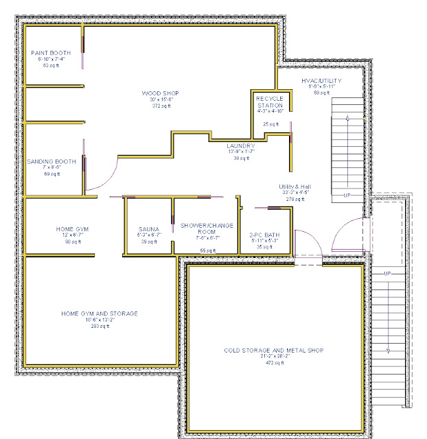 |
| Fig 8 - Basement |
Design Considerations:
- Contain all HVAC equipment.
- Provide Laundry facility where noise will not be disturbance to occupants. Also reduces flood hazard by not having it on upper floors (Holmes would be proud!).
- Provide space for home gym (first hurtle, actually using it is the hardest).
- Fulfill life long dream of a full wood shop.
- Provide Waste Vegetable Oil fuel processing station (upcoming blog entry).
- Provide for computer LAN vault.
- Provide for ample storage.
- Accommodate a Sauna.
Open Floor Truss Supplier?
Looking for a good open floor truss manufacturer for a project in the Greater Vancouver area (British Columbia). Any ideas?
Tuesday, 4 December 2012
Visualizing Wind Patterns
I remember multiple lectures during the BCIT BLDC 3050 & 3060 Building envelope courses that discussed the strange patterns wind can take when it hits a building. Well some smart individual figured out a way to visual it in real time.
Check out this cool video
Check out this cool video
Friday, 30 November 2012
SENWiEco continues their test run of the Prosoco R-Gaurd product line
SENWiEco continues their test drive of the liquid applied WRB/AB system called R-Guard from Prosoco. This is a 4 part liquid barrier applied to the exterior sheathing to form both the Water Resistant Barrier and the Air Barrier.
The first part of their system is called Joint & Seam and is used at the interface between any components that can move (either from moisture or temperature changes). You would use this product (that contains fibres to provide strength to the joint under movement) at the interface between the plywood sheathing and the stick structure around door and windows, to fillet around plumbing and electrical pipes, to fillet between the wall and floor or between two walls, and along all sheathing seams.
The next product in the R-Guard lineup is the Fast Flash product. Fast Flash is used in place of a self adhered membrane on the vertical surfaces of the sheathing and rough openings that may see a higher volume of moisture. Unlike SAM, it is vapour permeable so will not contribute to rotting around the rough openings that is so often seen with dwellings where a high volume of SAM has been applied. Although the manufacture recommends its use on window sills, SENWiEco cannot at this time recommend this application and instead recommend a water AND vapour tight membrane like PS45 at the window sill. We will discuss this issue more in a future post and provide our test results where we performed an extended inverted water test using the Fast Flash product.
Once the Fast Flash has been applied, you are then able to treat the field of the walls with the R-Guard Cat 5 roll on product. The product has gone through extensive testing and can withstand the forces of a Category 5 Hurricane.
Finally, as the final part of the R-Guard system, when the windows are installed you provide a air seal and water shedding surface at the interior face of the window frame using R-Guard Air Dam.
SENWiEco subjected our test assembly to -4500 Pa (equivalent of 185 Mph or 300 Kph winds) and did not experience any leaks through the sheathing joints and HVAC/Electrical/Plumbing penetrations. We did have two pinhole leaks around window clips and the window frame itself started to leak at that pressure. We will provide a follow up posting with links to videos of our tests once they are available.
In the meantime, we invite you to watch a series of videos capturing our trial run of the R-Guard system.
1) Application of R-Guard Joint & Seam
2) Application of R-Guard Fast Flash
3) Discussing the application of R-Guard Cat5
4) Detailing an exterior Electrical Outlet
(In hindsight, I would detail this differently to make it more attractive by making the wood 'box' only the width of the electrical outlet plus 3/8" each side for a caulking joint)
5) Detailing an exterior HVAC Termination/Intake
6) Discussing the consideration needed when installing a box style window
7) Detailing Window Sill using a Back Stop
8) Discussing the Head Flashing placement and Head and Jamb Trim considerations
9) Detailing Jamb Trims
10) Installing Head Flashing
11) Seal Sill Back Stop, Window Clips, and install Backer Rod
12) Installing R-Guard Air Dam
13) Discussing Failure at clips and ways to re-detail in a water tight fashion
14) Building a Poly Enclosure to test the Air and Water control layers in a wall assembly
15) Pressurized Smoke Test
16) Depressurized Water Test
17) Discuss Failure at Window Clip
18) BCIT BLDC 3060 Water Test - Passed at -1200 Pa
19) Site built differential pressure gauge
20) Mock up assembly is tested to -4500 Pa or 18" of Head Pressure!
This was phenomenal results for the R-Guard system and for the Cascadia windows. The only leaks around the windows were are locations where old sealant remnants had not been removed. We also suspect that the window frame joint was damaged when the window was cut out of the BCIT Mock-up. Even if it wasn't, this is very little water for a -4500 Pa pressure which represents winds this dwelling will never see!
Wednesday, 28 November 2012
We hit 1000 hits
Just a quick note to thank all you readers for visiting my blog. I reached 1000 hits today which is an excellent milestone considering the short period of time this blog has been up and the limited topics of conversation.
Thanks for reading and please let me know what you would like to read in upcoming entries.
I can advise that my house design is moving forward (slower than hoped but still at a reasonable pace). I will soon be able to post floor plans and advise the factors that were considered in their layout. I will then be moving on to the engineering of the floors and roof structures. I am aiming for plans submission and permit applications for Late February of 2013. I anticipate needing a couple of variances that I will discuss further in a future posting. I am crossing my fingers that this can be approved faster than the 4 months typically quoted, as I need to start by late May, or very early June at the latest, if I am to have any chance of getting the roof on before the winter rains. If this was not achievable, I would be delaying the start until the spring of 2014.
Once again, thanks for visiting and please check back often or better yet subscribe so that you are automatically notified of new postings.
Cheers!
The problem with architecture is architects!
Some of you who know me, know my general bias against the architectural profession. I have built up this bias over many years for many reasons, but primarily due to the lack of respect many of their designs show to good building science.
Well today was grounds to again support this bias and I just can't keep my thoughts contained. Against my better judgment, I attended the Sustainabuild conference in Vancouver which is geared towards the architectural community. My draw was one of the speakers - Murray Frank - who I highly respect and was one of the only real rays of sunshine in an otherwise cloudy and stormy day. Fortunately he provided a presentation on good science or my head would have exploded with all of the assaults to good building science presented throughout most of the day's balance.
Let me give you some examples. I just about bit through my tongue when one of the early presenters discussed Chicago's Aqua tower shown in the photos below and advised "we can design buildings that are able to capture solar energy".. "and get rid of excess heat within the building".
Are you kidding me?
The Aqua tower is an abomination to all good building science practices and pretty much eliminates the ability to separate the exterior from the interior environment due to its extreme solar bridging and moisture transport by means of the extended floor slabs. I can advise that in the heart of the summer, you still need to have the heat turned on during cloudy days (I have the unfortunate distinction of having stayed at the hotel during a recent vacation - my wife booked the place before I realized where it was).
But the tower won some awards and was designed by a women and is pursuing the LEED certification, so it must be a good thing - right?
Wiki states "Sustainability was an important factor in Aqua's design. Gang and her team refined the terrace extensions to maximize solar shading, and other sustainable features will include rainwater collection systems and energy-efficient lighting. The green roof on top of the tower base will be the largest in Chicago."
Why not try and make the building enclosure bullet proof before worrying about small energy contributors like lights and rainwater collection.
Green roofs have been proven many times to not be green (they often do not reduce storm runoff, make for poor performing insulation, often need to be watered to stay alive, are often poorly installed leading to leaks, and the list goes on). The only reason for them is a visual pleasantry and no one is going to see this one being on the top of one of the tallest buildings in the area.
The same presenter then tried to advise the room, towers are less green than low rises because they use more energy per cubic meter due to the need to "pump all that water up all those floors". A figure of 1100 units (believe it was kWh/m2/annun) was identified for the towers and a much lower figure was used in their example for low and mid rise units. This person was advocating that we take up more land for buildings, make the buildings shorter, and that the result would be that we needed less 'green' space and parks because there would be less shading from neighbouring buildings and I guess indicates people would be more comfortable staying in their little cubby holes.
Fortunately there was a presenter later in the day who represented the Marine Gateway project at Marine Drive and Cambie in Vancouver. He had actual numbers from the modelling of the development which were down around 100 units which represent a very attractive target and a well run efficient building. But what if he was not in the room. The first presenter's assertion that towers equated to energy inefficiency would have prevailed and could have started a whole new push by the architectural community based on poor concepts using inaccurate data.
Besides Murray's presentation, the only other ray of hope in the room for me, was the fellow who presented on the Cambie Corridor densification project and specifically the Marine Gateway project. This project appears to be a great step towards sustainable multi-family living. There is only 50% glazing in the residential and 51% in the commercial spaces (compared to 75%-90%+ for many downtown buildings). The presenter went on to say that the areas that are not glazed are heavily insulated. Finally a team with their priorities straight. Get the building envelope right and you will have a low energy and 'green' building.
An example was made early in the day that showed the lotus car and had the presenter discussing how beautiful the cars exterior was and the true marvel was how the engineers were able to fit everything that was NEEDED into that 'beautiful' shape to make that shape FUNCTIONAL.
I see this process as being the biggest fundamental flaw with the architectural community.
We need to abolish this process and instead first decide on our performance goals, define our building enclosure to meet those goals using good building science, and only then allow the architects into the fray to design the perceived 'beauty' into the buildings. But only up to the point that the client can afford, after committing to the performance objectives first, and only to the point that the architects design does not impend the designed enclosure that is needed to meet the performance objectives.
Only then will our building start to become legacies instead of liabilities and truly be 'green'!
Well today was grounds to again support this bias and I just can't keep my thoughts contained. Against my better judgment, I attended the Sustainabuild conference in Vancouver which is geared towards the architectural community. My draw was one of the speakers - Murray Frank - who I highly respect and was one of the only real rays of sunshine in an otherwise cloudy and stormy day. Fortunately he provided a presentation on good science or my head would have exploded with all of the assaults to good building science presented throughout most of the day's balance.
Let me give you some examples. I just about bit through my tongue when one of the early presenters discussed Chicago's Aqua tower shown in the photos below and advised "we can design buildings that are able to capture solar energy".. "and get rid of excess heat within the building".
Are you kidding me?
The Aqua tower is an abomination to all good building science practices and pretty much eliminates the ability to separate the exterior from the interior environment due to its extreme solar bridging and moisture transport by means of the extended floor slabs. I can advise that in the heart of the summer, you still need to have the heat turned on during cloudy days (I have the unfortunate distinction of having stayed at the hotel during a recent vacation - my wife booked the place before I realized where it was).
 |
| The Aqua Tower in Chicago - Photo by your author Summer 2012 |
 | |||||||
| Thermograph image showing the extreme heat bridging present in this building (Notice the 20º Celsius spread in temperatures) - Photo http://www.healthyheating.com |
Wiki states "Sustainability was an important factor in Aqua's design. Gang and her team refined the terrace extensions to maximize solar shading, and other sustainable features will include rainwater collection systems and energy-efficient lighting. The green roof on top of the tower base will be the largest in Chicago."
Why not try and make the building enclosure bullet proof before worrying about small energy contributors like lights and rainwater collection.
Green roofs have been proven many times to not be green (they often do not reduce storm runoff, make for poor performing insulation, often need to be watered to stay alive, are often poorly installed leading to leaks, and the list goes on). The only reason for them is a visual pleasantry and no one is going to see this one being on the top of one of the tallest buildings in the area.
The same presenter then tried to advise the room, towers are less green than low rises because they use more energy per cubic meter due to the need to "pump all that water up all those floors". A figure of 1100 units (believe it was kWh/m2/annun) was identified for the towers and a much lower figure was used in their example for low and mid rise units. This person was advocating that we take up more land for buildings, make the buildings shorter, and that the result would be that we needed less 'green' space and parks because there would be less shading from neighbouring buildings and I guess indicates people would be more comfortable staying in their little cubby holes.
Fortunately there was a presenter later in the day who represented the Marine Gateway project at Marine Drive and Cambie in Vancouver. He had actual numbers from the modelling of the development which were down around 100 units which represent a very attractive target and a well run efficient building. But what if he was not in the room. The first presenter's assertion that towers equated to energy inefficiency would have prevailed and could have started a whole new push by the architectural community based on poor concepts using inaccurate data.
Besides Murray's presentation, the only other ray of hope in the room for me, was the fellow who presented on the Cambie Corridor densification project and specifically the Marine Gateway project. This project appears to be a great step towards sustainable multi-family living. There is only 50% glazing in the residential and 51% in the commercial spaces (compared to 75%-90%+ for many downtown buildings). The presenter went on to say that the areas that are not glazed are heavily insulated. Finally a team with their priorities straight. Get the building envelope right and you will have a low energy and 'green' building.
An example was made early in the day that showed the lotus car and had the presenter discussing how beautiful the cars exterior was and the true marvel was how the engineers were able to fit everything that was NEEDED into that 'beautiful' shape to make that shape FUNCTIONAL.
I see this process as being the biggest fundamental flaw with the architectural community.
We need to abolish this process and instead first decide on our performance goals, define our building enclosure to meet those goals using good building science, and only then allow the architects into the fray to design the perceived 'beauty' into the buildings. But only up to the point that the client can afford, after committing to the performance objectives first, and only to the point that the architects design does not impend the designed enclosure that is needed to meet the performance objectives.
Only then will our building start to become legacies instead of liabilities and truly be 'green'!
Tuesday, 20 November 2012
Why do we continue to drill holes into our buildings?
I was recently driving by
yet another building with vapour ‘diffusion’ ports (VDP’s) and it got me
thinking:
Why do we continue to let our buildings be drilled full of holes?
I have always believed that the ports did not work based on previous information I had reviewed, and they are certainly not a recommendation made in the Best Practices Guide published by the Home Protection Office (HPO) in collaboration with some of the best engineering firms in the North America, firms like RDH, RJC, and Morrison Hershfield.
So why do a limited number of buildings still incorporate these ports in their designs?
First of all, we need to try and understand the intent of vapour diffusion ports. As I understand it, the intent is to help walls ‘dry out’ by allowing the wall assembly to ‘breathe’ more easily. The ports are intended to increase the breathability of the assembly by means of diffusion, over a solid sheathing base line. By ‘breathing’, we are referring to the wall’s ability to ‘lose’ moisture in a vapour form, by allowing that moisture to go ‘through’ a wall’s materials and evaporate into the outside air (low vapour pressure side). We say walls can ‘breathe’ if all of the materials on the low vapour pressure side (which can change direction depending on conditions) are vapour-open, or that they have a high permeability. In simple terms, this means that the pores of the material are large enough to allow a water molecule in vapour form to pass through the material. The mechanism of passing through the assembly is usually termed ‘diffusion’, but a review of Chapter 8 of Building Science for Building Enclosures by Straube/Burnett details that the actual mechanisms involved with moisture movement through a porous material are extremely complex and can involve surface diffusion, capillary action, evaporation, convection, absorbed moisture transport, etc. Even today, the flow of moisture through materials is not fully quantifiable by scientists or fully predictable. What is a provable fact is that in order for vapour diffusion to take place there needs to be a difference in vapour pressure across the two sides of the material (or assemblies) in question.
So are these ports working as intended?
How wide a range does each port have? Are there other mechanisms at
work? Is this an effective drying
strategy?

Why do we continue to let our buildings be drilled full of holes?
I have always believed that the ports did not work based on previous information I had reviewed, and they are certainly not a recommendation made in the Best Practices Guide published by the Home Protection Office (HPO) in collaboration with some of the best engineering firms in the North America, firms like RDH, RJC, and Morrison Hershfield.
So why do a limited number of buildings still incorporate these ports in their designs?
First of all, we need to try and understand the intent of vapour diffusion ports. As I understand it, the intent is to help walls ‘dry out’ by allowing the wall assembly to ‘breathe’ more easily. The ports are intended to increase the breathability of the assembly by means of diffusion, over a solid sheathing base line. By ‘breathing’, we are referring to the wall’s ability to ‘lose’ moisture in a vapour form, by allowing that moisture to go ‘through’ a wall’s materials and evaporate into the outside air (low vapour pressure side). We say walls can ‘breathe’ if all of the materials on the low vapour pressure side (which can change direction depending on conditions) are vapour-open, or that they have a high permeability. In simple terms, this means that the pores of the material are large enough to allow a water molecule in vapour form to pass through the material. The mechanism of passing through the assembly is usually termed ‘diffusion’, but a review of Chapter 8 of Building Science for Building Enclosures by Straube/Burnett details that the actual mechanisms involved with moisture movement through a porous material are extremely complex and can involve surface diffusion, capillary action, evaporation, convection, absorbed moisture transport, etc. Even today, the flow of moisture through materials is not fully quantifiable by scientists or fully predictable. What is a provable fact is that in order for vapour diffusion to take place there needs to be a difference in vapour pressure across the two sides of the material (or assemblies) in question.
In researching this
topic I came across two related studies performed in the late 1990’s after the
leaky condo crisis. The first study
titled The Envelope Drying Rates Analysis Study looked at the abilities of various wall assemblies to dry out (in lab
conditions) while changing up components like sheathing materials, capillary
break depth, and sheathing membrane materials.
What I found most surprising was that none of the panels were dry to
safe levels (below 20%) even at the end of the 2000 hour study.
The second study
titled Evaluation of Vapour Diffusion Ports on Drying of Wood-Frame Walls Under Controlled Conditions utilized
the same panels, but drilled out vapour diffusion ports on some of the panels and then
re-ran parts of the experiment to look at the effectiveness of the vapour
diffusion ports specifically. What was
again remarkable was that, although the VDP’s did provide a minor increase in
the initial drying rate of the OSB panels (no change in the rate of drying in
the plywood panels which was already higher than OSB with or without the VDP’s
), all of the panels (OSB & Plywood) again contained areas with dangerous
levels of wood moisture at the end of the study (which repeated the first
studies results).
After reviewing these
studies and Building Science for Building
Enclosures, I now have a better grasp on
the true mechanisms at work with vapour ‘diffusion’ ports, and only a little of
the process actually involves diffusion.
Where the ports have been effective to any measurable level, some form
of convection must take place in conjunction with lots of capillary movement.
Let’s look at these mechanisms in a bit more detail.
Convection (or air
movement) can occur because of air leakage through an assembly from the high to
low pressure side. It can also occur by
means of the convective currents that can develop within each stud bay if a low
density batt and fill insulation (i.e. fibreglass) is used. Neither of these mechanisms is desirable from
an enclosure performance standpoint. Convection forces within the wall assembly
can deliver moisture-rich air derived from the ‘wettest’ parts of the wall
assembly (studs, plates, & insulation) and deposit that moisture onto the back
side of the sheathing (which can allow a generalized increased drying rate
from the sheathing by means of diffusion to the outside air). Where that
moisture is close enough to a port, there can also be a localized marginal increase
in permeability over the base-line sheathing.
This can help dry an assembly if no additional moisture is introduced
through the convection mechanism, but air leakage through an assembly can often
bring with it high levels of moisture into the assembly from the interior of
the dwelling. And once in the assembly,
that moisture can then condense on any of the wall elements with surface
temperatures that are below the dew point of the leaking air. (See my July/2012
and March/2012 blog entries for more info on dew points and moisture in wall
assemblies). Stud bay convective
currents often create ‘air pumps’ that can lead to cold interior walls and thermal
bridging, causing additional heat loss (you are bypassing the insulation by
delivering heat to the outside sheathing and taking it from the inside wall
board).
Now lets look at
capillary and diffusion forces in connection with these ports - as areas close
to the ports dry out via diffusion through the holes in the sheathing (which
have a higher permeability because the moisture has to only diffuse through the
sheathing membrane and not though the membrane AND the sheathing), or by air
leakage through the holes (because the sheathing membrane has been damaged or
is not sealed as an air control layer), that moisture is replaced by wetter neighbouring regions. The process continues until, over time, the
moisture levels within the assembly equalize.
The assembly as a whole is also trying to equalize with its lower vapour
pressure neighbours (so in this geographical region, usually to the
outside). The entire process continues
until all regions have the same vapour pressure (something that in practice
rarely occurs as there is always changing interior and exterior humidity and
temperatures which lead to changing vapour pressures).
The problem however, with
relying on the diffusion and capillary forces alone is that, although capillary
forces are faster than diffusion, both forces will not dry a wall assembly out fast
enough to be an effective deterrent to decay and fungal growth. This was confirmed in both studies, where
portions of every test panel still had wood moisture levels in the danger zone
for promoting (not just maintaining) rot, even after close to three months,
regardless if VDP’s were installed or not!
These studies only had one wetting period - What happens when you have repeated introductions of moisture (interior
air leakage, exterior leaks, or plumbing leaks)?
What does all of this mean? Are these results important?
Let’s look at where
moisture can originate and how effective VDP’s are at addressing that moisture
source. There are five causes that come
to mind:
- Initial wood moisture elevated during construction due to the rain forest we are building in,
- Bulk water entry (after construction) from the exterior around poorly detailed penetrations and even through vapour diffusion ports,
- Bulk water entry from water pipe and drain leaks within the assembly,
- Air leakage through the assembly causing condensation,
- Vapour diffusion into the assembly (usually caused by excessive RH% levels in the dwelling’s interior and/or inadequate vapour control layer)
The easiest way to
address the first cause is to leave the drywall, poly, and insulation off the
interior of the structure until the assembly dries out. The problem is that construction schedules
are so tight; we typically do not allow adequate drying time. If we are unable to allow sufficient time for
a wall to naturally dry out before boarding, then we need accelerate the
process by adding heat and air movement to the mix (and in some extreme cases, de-humidification). If we rely on the VDP’s alone to allow the wall to diffuse
the moisture out and close up the assembly in a wet state, we could be waiting
many months for safe moisture levels within the assembly to occur, and by that
time a healthy crop of fungi would most likely have already taken root leaving
us with a sick wall assembly.
VDP’s
Score: F
The second and third
mechanism only has one solution – stop the bulk water entry! There is no effective strategy to manage bulk
water entry once it has occurred. Even BC’s Rain-Screen requirements will not
solve repeated bulk water entry into a wall
assembly. You must stop it at the source.
VDP’s Score: F
The fourth mechanism of
moisture entry is also somewhat simple to address. Stop the air flow through
the assembly by means of an effective air control layer. Unless you stop the air flow and the
resulting condensation, the rate of moisture input will again often overwhelm the slow
drying rate of a wall assembly by means of diffusion only, with or without VDP’s.
VDP’s Score: C- down to F (depending on
the incoming moisture levels and type of sheathing installed).
The final mechanism also
has an easy solution in most dwellings.
Control the interior humidity by means of mechanical ventilation and/or
install an effective vapour control layer in the assembly.
VDP’s Score: C down to F (depending on incoming moisture levels
and type of sheathing installed).
Let’s summarize this information. If a VDP is sealed against
airflow, we are generally relying on diffusion and capillary forces and
possibly stud bay convection currents to help dry out a wall assembly. However these processes are slow, and the VDP’s
only account for a limited improvement of drying potential over base
lines. As a result the assembly would
typically not dry out in time to prevent decay regardless of the presence of
the VDP’s. If we allow air movement to
occur through the ports, the air movement that would occur through the assembly
can often bring with it levels of moisture that are easily able to overcome the
limited additional drying capabilities represented by the VPD’s.
Are there downsides to including VDP’s “just in case”?
Well, it turns out these holes are
usually conveniently placed just below windows and other enclosure penetrations
where any incorrectly detailed flashing or membrane (like the holes drilled
through all the water-resistant layers in the photo - below left) could direct water
along the surface of the sheathing and into the wall assembly through these
strategically placed inward water highways!
Is this really a wise practice?
We need to stop this
insanity. I put a challenge out to all
of the engineering firms that know better.
Please stop allowing your buildings to be
drilled full of holes. Start
taking the architects, building officials, and contractors to task to stop this
poor building practice. Start educating the teams you work with and let’s start building smarter!
WHAT WERE THEY THINKING?
Figure 1
Vapour ‘Diffusion’ ports (holes in sheathing that act as inward water highways)
on buildings under construction in North Vancouver, BC
Subscribe to:
Posts (Atom)