Hey folks, sorry for the time span since the last post. I have been concentrating on keeping my building journal up to date.
As I recently have had some free time due to yet another set of medical setbacks, I recently finished editing and uploading a video showing my process of adhering the Roxul ComfortBoardIS mineral wool insulation to my ICF foundation.
The Soprema Colphene Torch'N Stick membrane would typically be used on a site formed concrete foundation, but because I am using a ICF product from Durisol (made from mineralized wood fibre and cement slurry), I too could use this torch on membrane (a process that would destroy conventional EPS foam ICF forms). The 'tacking' of the insulation to the membrane is only a light mechanical bond and is only suitable for a temporary support of the insulation (or dimple board and other protection sheets) until the backfill takes place. You would not be able to use the method for a permanent attachment in an above grade assembly.
Once the insulation was attached, I then fastened dimple sheet to the insulation, installed a granular drainage plain, geotextile, and then compacted backfill. You can read about these steps on my "coming out of the hole" journal entry.
The overall foundation assembly will have multiple layers of safety and will be very durable, but the installation is costly and very time consuming. I can understand why many of these steps are not incorporated into most residential construction. But then, most residential below grade basements are wet to some degree. As my friend Murray Frank often says "You never hear a comment 'It smells as good as a basement'".
Thanks for visiting folks. I will hopefully post a review of all the products I have used to create my foundation walls within the next few weeks. A majority of the products get a thumbs up from a technical standpoint, but one in particular is a two thumbs down with extreme prejudice. I encourage you to subscribe if you want to be notified of when this review is posted.
Showing posts with label Passive House. Show all posts
Showing posts with label Passive House. Show all posts
Monday, 31 August 2015


Friday, 29 May 2015
Air Leakage of Old House - Does it matter?
*** Update - Upon further reflection of this topic, I do feel there is one additional reason to perform energy upgrades and discuss it in my project journal http://www.theenclosure.ca/windy-house ***
This blog entry will analyze the air leakage of a 1954 house and relate that to the energy use and durability of the house.
Before I started tearing down my 1954 single storey 1500 sq ft bungalow to make way for theEnclosure.ca, I decided to have the house tested for air leakage by Michael and Deborah from H&H small home solutions inc (hhsss at shaw dot ca). H&H typically perform leakage testing to determine the EnerGuide rating for new construction, so this was going to be a new experience for them (and their blower door).
They came by in late March of 2014 after I had moved out but before I had completely emptied the house and before any deconstruction had been performed. The house was prepped by sealing the wood burning fireplace insert, range hood, and the through-wall mailbox before setting up the blower door.
We first ran the door in a B configuration and were unable to get up to the final test pressure of -50 Pa. But even in this configuration we got some scary results. I had not really made any great attempts to air seal this house over the years. There was weather stripping on 1 of the 3 doors, and the cedar siding had each coarse sealed to the next and the siding sealed to most of the window and door frames. But no attempts had been made to seal the interior interface with the attic plane and 1 of the doors had a cat door in it and the main door itself had very large gaps around it.
Prior to starting the test I had predicted an air leakage around 8-10 ACH (Air Changes per hour) @ -50 Pa, but early in the test we could tell it was going to be well above this. Deborah could tell just from the sound the fan was making (there previous worst house they tested was 11 ACH @ -50 Pa which was scary as it was new construction).
Right off the bat we reached 28 air exchanges at only -15 Pa! To give you an idea, 15 Pa relates to a wind speed of only 11 MPH. In the fall, I regularly recorded winds speeds on the property at this speed or higher so during those events all of that CONDITIONED air in the house was potentially changing over 28 times every hour. That is a lot of extra load on the heating plant and also explained the drafts my wife typically was feeling.
Over the next hour or so we tested at various configurations until we ran the fan at full open configuration (no restrictor plates). Only then could we get enough air volume to allow us to reach the target test pressure of -50 Pa. AT the full test pressure we recorded an air leakage of 21.74 ACH -50Pa.
Now wait, some of you may have noticed that that is less air leakage than what we observed at only -15 Pa. How is this possible you say?
Well, it is actually quite common. As more and more negative pressure is placed on a dwelling, the two surfaces on each side of an air path (leak) can start to come together. Eventually they can close up tight and stop that leak. This why I have a bit of an issue (actually quite a bit), of testing dwellings at -50 Pa. This relates to a wind speed of 20 Mph which is much higher than some locations would experience on a regular basis and much lower than other locations average wind speeds. As such, it is my opinion that their should be a standard test pressure PER geographical region. This could be a table much like the climate zone charts, but would be based on the average yearly mean wind speeds for a specific area. Homes in higher wind speed regions should be tested at higher pressures than homes in lower wind speed regions.
(Side bar - the reason the wind speed is important is that it is this force that will effect the pressures on a dwelling. Yes a house can depressurize under mechanical ventilation, but these are usually infrequent where wind depressurization or pressurization of the dwelling could occur for months at a time in windy locations).
So - these tests showed that the house was VERY leaky. What does that mean in terms of heating bills, comfort, and building durability.
Heating Bills
The truth is, this air leakage did not really make a huge difference in energy costs. My heating bills (for space and domestic hot water) were typically well under $2000 a year (We are under $2000 for both gas AND electrical use). As I am a heavy bath user, it is safe to say aprox 40% of this was domestic hot water use. This leaves an estimated $1000 in annual space heating costs. That works out to less than $100 a month, or well less than the cost of a weekend dinner out.
We typically had the heat set for 72-73F in the wintertime and basically did not tough the thermostat all year. It was not uncommon for the heat to come on during cold late spring and early fall evenings. We did however use a programmable thermostat that was set to come on at 7 AM, step down to about 65F at 8:30 AM, come back to temp at 4 PM, and step back down to about 68F at 11:30 PM. This was only partially for energy savings. The night time set backs were used because we had hydronic heating through large built-in wall registers (1-2 per room) via a 1980's gas boiler. The pipes went through and rubbed on the wood sub-floor assembly, so if the heat came on during the night the 'clicking' would wake me up. So we partially closed the bedroom door (so cats could still get in and out and not cause another source of nighttime wake-ups) and used an electric oil heater to maintain a comfortable temp in the bedroom.
While air tightness is important, it will not make a huge difference to your pocket book unless you have a very large and leaky house.
Comfort
The air leakage did however make a big difference in occupant comfort and should, in my opinion, be the biggest (and probably only) reason to upgrade an older home. The house was uncomfortable to sit in near any exterior wall in the winter months due to the drafts present. I was quite surprised when I saw how leaky the fixed, but home made, windows in the living room were. The builder had just placed the single pane of window glass against a wood surface and clamped it with a second wood component. At -15Pa, the wind just whistled through these locations. There is no question, that making the house more air tight would have made the house more comfortable.
Durability
Normally when one discusses the reasons for making a dwelling air tight, it is in the context of a 'modern' home with current levels of code required insulation. With modern levels of insulation, it is critical to ensure that air leakage does not occur, in order to prevent interior air leaking into the wall or roof assembly and condensing on cold sheathing. Left unchecked, this will often lead to mold and rot within the assembly.
The key here is the qty and location of the insulation. As soon as enough insulation is placed inside of the sheathing to allow the sheathing to cool down below the dew point of the interior air, you now have an assembly with a very high liability should any appreciable amount of air leak into that assembly from the conditioned interior. This is because air currents are the #1 mover of moisture next to bulk water leaks caused by plumbing leaks or incorrectly detailed cladding or roofs that permit bulk rain water entry into the assembly.
But in older houses like the one I took down (which had ZERO insulation in the walls), there is not enough insulation present to block the heat loss from the house enough to allow the sheathing to get to the dangerous dew point conditions. If you never reach the dew point, you can have huge amounts of moisture moving into the wall via air leakage and never have to worry about it because it stays in vapour form and just moves on through either to the outside of the dwelling or back into the inside. There is never liquid water that results from this air leakage. This is the reason why older homes have performed so well over many decades without the presence of air barriers, vapour barriers, or even effective water shedding surfaces. The heat loss has always been enough to 'cook' any accumulated moisture out of the assembly.
Conclusion
We have identified in this article that there is not a huge financial penalty for a leaky house. In my case, the costs per month for space heating were under $100/month in what is considered a cold-heating-dominated climate. This $1200 annual investment would not get very far in paying for a deep energy retrofit which typically would cost 10's of thousands of dollars. Lets say you could reduce the heating load even as much as 75% (purely speculative and most likely could not meet), this would represent $900 annual contribution to renovation costs.
A REALLY cheap stud level renovation for my home (including new windows and doors) would have been at least $60K (going to need to rip out parts of bathrooms and kitchens so most likely will totally renovate those rooms - my budget of $60 assumes very low end cabinets for these rooms).
A very intensive attic floor plane sealing regime would have been at least $15K (not going to do this process without bringing attic up to current insulation levels when done).
At a highly inflated $900 annual savings, these two projects would have a 66 and 17 year payback respectively. The attic plane sealing payback would most likely be much longer as only sealing this plane would probably represent only 50-70% of all air leakage present and therefore there would be reduced energy savings.
And my house did not represent an unusual annual energy bill. This US Energy Summary shows that for the West, the average annual winter heating bill per household varies between $1300 and $800 depending on year.
In the end, due to our really low energy costs, and the likely hood that they will not appreciably escalate for many decades due to Government interference, it makes very little sense to upgrade an existing homes energy performance for personal financial savings. Therefore the type of renovation needed to reduce air leakage or increase thermal performance, only makes sense if the home is being renovated anyway for cosmetic or occupant comfort reasons.
On a separate track - this logic also holds true when analyzing extreme new construction programs like Passive House. The costs to reach passive house levels of energy reduction will not be paid back over the lifespan of the dwelling in most cases. The added detriment of these programs is that the embodied energy of the insulation products built into these dwellings also do not have a pay back within the lifespan of the dwelling. Instead for new construction, it makes more sense to build a "Pretty Good House" (coined by Joe Lstiburek) and then use the excess capital available to either contribute to distributed or on-site energy generation.
It is however critical that air leakage be reduced down to a minimum (experts do not agree how little is adequate - but the number is somewhere between 1ACH+/-50 and 3ACH+/-50) for new construction or energy retrofits IF, you have built an assembly with enough insulation inboard of the sheathing to cause the sheathing to cool down to the dew point potential of any leaking interior air. If you build a safer assembly with the insulation outboard of the sheathing (or enough outboard to maintain the sheathing above the dew point potential), then while air leakage is still important to address from an energy loss standpoint (the costs to get it right during construction are minimal and will be paid back by reduced energy usage), it usually will not cause a durability concern for the assembly. This of course is all from the perspective of a heating dominated climate. The direction of flow and order of layers for the assembly are different in a cooling dominated or mixed climate.
This blog entry will analyze the air leakage of a 1954 house and relate that to the energy use and durability of the house.
Before I started tearing down my 1954 single storey 1500 sq ft bungalow to make way for theEnclosure.ca, I decided to have the house tested for air leakage by Michael and Deborah from H&H small home solutions inc (hhsss at shaw dot ca). H&H typically perform leakage testing to determine the EnerGuide rating for new construction, so this was going to be a new experience for them (and their blower door).
They came by in late March of 2014 after I had moved out but before I had completely emptied the house and before any deconstruction had been performed. The house was prepped by sealing the wood burning fireplace insert, range hood, and the through-wall mailbox before setting up the blower door.
We first ran the door in a B configuration and were unable to get up to the final test pressure of -50 Pa. But even in this configuration we got some scary results. I had not really made any great attempts to air seal this house over the years. There was weather stripping on 1 of the 3 doors, and the cedar siding had each coarse sealed to the next and the siding sealed to most of the window and door frames. But no attempts had been made to seal the interior interface with the attic plane and 1 of the doors had a cat door in it and the main door itself had very large gaps around it.
Prior to starting the test I had predicted an air leakage around 8-10 ACH (Air Changes per hour) @ -50 Pa, but early in the test we could tell it was going to be well above this. Deborah could tell just from the sound the fan was making (there previous worst house they tested was 11 ACH @ -50 Pa which was scary as it was new construction).
Right off the bat we reached 28 air exchanges at only -15 Pa! To give you an idea, 15 Pa relates to a wind speed of only 11 MPH. In the fall, I regularly recorded winds speeds on the property at this speed or higher so during those events all of that CONDITIONED air in the house was potentially changing over 28 times every hour. That is a lot of extra load on the heating plant and also explained the drafts my wife typically was feeling.
Over the next hour or so we tested at various configurations until we ran the fan at full open configuration (no restrictor plates). Only then could we get enough air volume to allow us to reach the target test pressure of -50 Pa. AT the full test pressure we recorded an air leakage of 21.74 ACH -50Pa.
Now wait, some of you may have noticed that that is less air leakage than what we observed at only -15 Pa. How is this possible you say?
Well, it is actually quite common. As more and more negative pressure is placed on a dwelling, the two surfaces on each side of an air path (leak) can start to come together. Eventually they can close up tight and stop that leak. This why I have a bit of an issue (actually quite a bit), of testing dwellings at -50 Pa. This relates to a wind speed of 20 Mph which is much higher than some locations would experience on a regular basis and much lower than other locations average wind speeds. As such, it is my opinion that their should be a standard test pressure PER geographical region. This could be a table much like the climate zone charts, but would be based on the average yearly mean wind speeds for a specific area. Homes in higher wind speed regions should be tested at higher pressures than homes in lower wind speed regions.
(Side bar - the reason the wind speed is important is that it is this force that will effect the pressures on a dwelling. Yes a house can depressurize under mechanical ventilation, but these are usually infrequent where wind depressurization or pressurization of the dwelling could occur for months at a time in windy locations).
So - these tests showed that the house was VERY leaky. What does that mean in terms of heating bills, comfort, and building durability.
Heating Bills
The truth is, this air leakage did not really make a huge difference in energy costs. My heating bills (for space and domestic hot water) were typically well under $2000 a year (We are under $2000 for both gas AND electrical use). As I am a heavy bath user, it is safe to say aprox 40% of this was domestic hot water use. This leaves an estimated $1000 in annual space heating costs. That works out to less than $100 a month, or well less than the cost of a weekend dinner out.
We typically had the heat set for 72-73F in the wintertime and basically did not tough the thermostat all year. It was not uncommon for the heat to come on during cold late spring and early fall evenings. We did however use a programmable thermostat that was set to come on at 7 AM, step down to about 65F at 8:30 AM, come back to temp at 4 PM, and step back down to about 68F at 11:30 PM. This was only partially for energy savings. The night time set backs were used because we had hydronic heating through large built-in wall registers (1-2 per room) via a 1980's gas boiler. The pipes went through and rubbed on the wood sub-floor assembly, so if the heat came on during the night the 'clicking' would wake me up. So we partially closed the bedroom door (so cats could still get in and out and not cause another source of nighttime wake-ups) and used an electric oil heater to maintain a comfortable temp in the bedroom.
While air tightness is important, it will not make a huge difference to your pocket book unless you have a very large and leaky house.
Comfort
The air leakage did however make a big difference in occupant comfort and should, in my opinion, be the biggest (and probably only) reason to upgrade an older home. The house was uncomfortable to sit in near any exterior wall in the winter months due to the drafts present. I was quite surprised when I saw how leaky the fixed, but home made, windows in the living room were. The builder had just placed the single pane of window glass against a wood surface and clamped it with a second wood component. At -15Pa, the wind just whistled through these locations. There is no question, that making the house more air tight would have made the house more comfortable.
Durability
Normally when one discusses the reasons for making a dwelling air tight, it is in the context of a 'modern' home with current levels of code required insulation. With modern levels of insulation, it is critical to ensure that air leakage does not occur, in order to prevent interior air leaking into the wall or roof assembly and condensing on cold sheathing. Left unchecked, this will often lead to mold and rot within the assembly.
The key here is the qty and location of the insulation. As soon as enough insulation is placed inside of the sheathing to allow the sheathing to cool down below the dew point of the interior air, you now have an assembly with a very high liability should any appreciable amount of air leak into that assembly from the conditioned interior. This is because air currents are the #1 mover of moisture next to bulk water leaks caused by plumbing leaks or incorrectly detailed cladding or roofs that permit bulk rain water entry into the assembly.
But in older houses like the one I took down (which had ZERO insulation in the walls), there is not enough insulation present to block the heat loss from the house enough to allow the sheathing to get to the dangerous dew point conditions. If you never reach the dew point, you can have huge amounts of moisture moving into the wall via air leakage and never have to worry about it because it stays in vapour form and just moves on through either to the outside of the dwelling or back into the inside. There is never liquid water that results from this air leakage. This is the reason why older homes have performed so well over many decades without the presence of air barriers, vapour barriers, or even effective water shedding surfaces. The heat loss has always been enough to 'cook' any accumulated moisture out of the assembly.
Conclusion
We have identified in this article that there is not a huge financial penalty for a leaky house. In my case, the costs per month for space heating were under $100/month in what is considered a cold-heating-dominated climate. This $1200 annual investment would not get very far in paying for a deep energy retrofit which typically would cost 10's of thousands of dollars. Lets say you could reduce the heating load even as much as 75% (purely speculative and most likely could not meet), this would represent $900 annual contribution to renovation costs.
A REALLY cheap stud level renovation for my home (including new windows and doors) would have been at least $60K (going to need to rip out parts of bathrooms and kitchens so most likely will totally renovate those rooms - my budget of $60 assumes very low end cabinets for these rooms).
A very intensive attic floor plane sealing regime would have been at least $15K (not going to do this process without bringing attic up to current insulation levels when done).
At a highly inflated $900 annual savings, these two projects would have a 66 and 17 year payback respectively. The attic plane sealing payback would most likely be much longer as only sealing this plane would probably represent only 50-70% of all air leakage present and therefore there would be reduced energy savings.
And my house did not represent an unusual annual energy bill. This US Energy Summary shows that for the West, the average annual winter heating bill per household varies between $1300 and $800 depending on year.
In the end, due to our really low energy costs, and the likely hood that they will not appreciably escalate for many decades due to Government interference, it makes very little sense to upgrade an existing homes energy performance for personal financial savings. Therefore the type of renovation needed to reduce air leakage or increase thermal performance, only makes sense if the home is being renovated anyway for cosmetic or occupant comfort reasons.
On a separate track - this logic also holds true when analyzing extreme new construction programs like Passive House. The costs to reach passive house levels of energy reduction will not be paid back over the lifespan of the dwelling in most cases. The added detriment of these programs is that the embodied energy of the insulation products built into these dwellings also do not have a pay back within the lifespan of the dwelling. Instead for new construction, it makes more sense to build a "Pretty Good House" (coined by Joe Lstiburek) and then use the excess capital available to either contribute to distributed or on-site energy generation.
It is however critical that air leakage be reduced down to a minimum (experts do not agree how little is adequate - but the number is somewhere between 1ACH+/-50 and 3ACH+/-50) for new construction or energy retrofits IF, you have built an assembly with enough insulation inboard of the sheathing to cause the sheathing to cool down to the dew point potential of any leaking interior air. If you build a safer assembly with the insulation outboard of the sheathing (or enough outboard to maintain the sheathing above the dew point potential), then while air leakage is still important to address from an energy loss standpoint (the costs to get it right during construction are minimal and will be paid back by reduced energy usage), it usually will not cause a durability concern for the assembly. This of course is all from the perspective of a heating dominated climate. The direction of flow and order of layers for the assembly are different in a cooling dominated or mixed climate.
Wednesday, 12 November 2014
Choosing Materials
The green building movement makes a big deal about choosing the right materials to ensure a product can be reused or returned to the raw material market at the end of the life-cycle. The end goal is of course to reduce the embodied energy of the project.
While this is a lofty ideal and worth pursuing, a reality check often shows that while a material is technically recyclable, there often (usually) not programs in place to actually process the used material. During the deconstruction of my house, I ran into two good examples.
My kitchen floor was pure linoleum tiles (essentially linseed oil). This is a product that can be composted or used as fuel for large scale heating boilers. But in my region, there was no program set up to process the product and I ended up taking it to the landfill (I did not have the facilities to grind up and compost myself).
The second product I failed to recycle was all of the plastic pipe I salvaged from below grade. This included PVC drainage pipe, PVC irrigation pipe, and ABS sewer pipe. For this commodity, there was a program in place to recycle the material, but only if it was VERY clean (think like new). The process available could not handle pipe with any dirt or other sediment on it. SO in the end, it too had to go to the landfill.
While we should endeavour to reduce our footprint on the planet and choose materials with lower embodied energy, we should also ensure that the materials we do choose are the most suited to the application.
I see too many 'green' building designs that choose a 'green' product due to a promised carbon footprint as the primary focus, without ensuring the product will be durable long term in service. This often will result in the need to replace the product after a very short life cycles. Even if the product can be returned back to the raw material supply chain, this still represents an increased burden on the planet compared to a competitive product that while being less 'green', is more durable in service. And if the 'green' product cannot be returned to the supply chain, you are just that much further behind.
Instead, my focus is to start at the most durable end of the spectrum and then try to pick products with lower embodied energy characteristics from the high performance candidates, AND install the products per best practices to ensure they are as useful and durable as possible.
My long term hope is that the cost of new materials becomes so high that even the main stream players in the market see recycling as a no-brainer. This would address the fact that right now, recycling often does not make sense from strictly a financial platform. However part of the problem is also the technical challenges in recycling a product.
Fortunately, there is some visionaries that have been working for many years to solve some of these hurdles. Mike Biddle has been working on a system that can separate bulk shredded plastics into the different colours and materials solving one of the biggest stumbling blocks to mass recycling of plastics (read PopSci article for full storey). The beauty of his system is that this is all done in N.A., saving the need to ship offshore, via an automated process (no high labour costs). By keeping the product on our shores, we reduce the pollution our society is creating within poorer countries.
Lets hope others are working on the myriad of other materials we as a society currently just discard.
While this is a lofty ideal and worth pursuing, a reality check often shows that while a material is technically recyclable, there often (usually) not programs in place to actually process the used material. During the deconstruction of my house, I ran into two good examples.
My kitchen floor was pure linoleum tiles (essentially linseed oil). This is a product that can be composted or used as fuel for large scale heating boilers. But in my region, there was no program set up to process the product and I ended up taking it to the landfill (I did not have the facilities to grind up and compost myself).
The second product I failed to recycle was all of the plastic pipe I salvaged from below grade. This included PVC drainage pipe, PVC irrigation pipe, and ABS sewer pipe. For this commodity, there was a program in place to recycle the material, but only if it was VERY clean (think like new). The process available could not handle pipe with any dirt or other sediment on it. SO in the end, it too had to go to the landfill.
 | |||
| Misc Pipe and Plastic that was not accepted at recycling facility. |
I see too many 'green' building designs that choose a 'green' product due to a promised carbon footprint as the primary focus, without ensuring the product will be durable long term in service. This often will result in the need to replace the product after a very short life cycles. Even if the product can be returned back to the raw material supply chain, this still represents an increased burden on the planet compared to a competitive product that while being less 'green', is more durable in service. And if the 'green' product cannot be returned to the supply chain, you are just that much further behind.
Instead, my focus is to start at the most durable end of the spectrum and then try to pick products with lower embodied energy characteristics from the high performance candidates, AND install the products per best practices to ensure they are as useful and durable as possible.
My long term hope is that the cost of new materials becomes so high that even the main stream players in the market see recycling as a no-brainer. This would address the fact that right now, recycling often does not make sense from strictly a financial platform. However part of the problem is also the technical challenges in recycling a product.
Fortunately, there is some visionaries that have been working for many years to solve some of these hurdles. Mike Biddle has been working on a system that can separate bulk shredded plastics into the different colours and materials solving one of the biggest stumbling blocks to mass recycling of plastics (read PopSci article for full storey). The beauty of his system is that this is all done in N.A., saving the need to ship offshore, via an automated process (no high labour costs). By keeping the product on our shores, we reduce the pollution our society is creating within poorer countries.
Lets hope others are working on the myriad of other materials we as a society currently just discard.
 |
| Mike Biddle has developed an automated (IE cheap - labour free) method of allowing plastic materials to be ground up on mass and then separated into the individual colour and materials making up that mass. |
Wednesday, 15 October 2014
Does PassiveHaus make sense?
Just a short update to showcase an article at Green Building Adviser that perfectly sums up the conclusions I made about the Passive House program and why I cancelled my plans to build to that standard.
The author of the article, found at www.greenbuildingadvisor.com/blogs/dept/musings/it-s-not-about-space-heating, tracked the actual energy use of several homes in Massachusetts and has determined that even a modest investment in insulation and air tightness (termed a pretty good house by Joe Lstiburek) is more than enough to reduce the heating and cooling loads to the point where it makes more sense to concentrate on plug and domestic hot water loads as is shown in the below graphic.

Extracted from http://www.greenbuildingadvisor.com/sites/default/files/images/Rosenbaum%20-%20Graph%20of%20Eliakims%20Way%20data%20copy.preview.jpg
The real world data monitoring has also shown that the assumptions made in the PHPP (the modelling system for PassiveHaus) are often wrong. The author states, “PHPP assumes 6.6 gallons [25 liters] of hot water a day per person, but that’s not enough for normal Americans.”
I jumped on board the PassiveHaus train for about a year in the early design stages of my upcoming build. It was easy to be swept up in the well polished program and fall in love with the projected savings. But as I became better and better educated on building science, source energy, and embodied energy, I felt their were huge holes in the program. The underlying principles of air tightness and thermal bridge free construction were sound, but in my view the chase for heating and cooling reductions bypassed the sweet spot where it made much more sense, from an embodied energy and a cost point of view, to look at on site production than further reduction. The biggest stumbling block was the claimed 10-15% added build cost to reach PH when in reality it is much closer to 200% on average when comparing to a code min house (which after all is what the majority of homes in North America are built to).
In the end I decided to build a "pretty good house" and will monitor energy loads once occupied and then model whether or not I reached the sweet spot between reduction and production.
Thanks for visiting. For the current status of the build please visit http://www.theenclosure.ca/project-journal/
PS: For an excellent article on why more insulation is not always better, read http://www.greenbuildingadvisor.com/blogs/dept/building-science/diminishing-returns-adding-insulation
The author of the article, found at www.greenbuildingadvisor.com/blogs/dept/musings/it-s-not-about-space-heating, tracked the actual energy use of several homes in Massachusetts and has determined that even a modest investment in insulation and air tightness (termed a pretty good house by Joe Lstiburek) is more than enough to reduce the heating and cooling loads to the point where it makes more sense to concentrate on plug and domestic hot water loads as is shown in the below graphic.
Extracted from http://www.greenbuildingadvisor.com/sites/default/files/images/Rosenbaum%20-%20Graph%20of%20Eliakims%20Way%20data%20copy.preview.jpg
The real world data monitoring has also shown that the assumptions made in the PHPP (the modelling system for PassiveHaus) are often wrong. The author states, “PHPP assumes 6.6 gallons [25 liters] of hot water a day per person, but that’s not enough for normal Americans.”
I jumped on board the PassiveHaus train for about a year in the early design stages of my upcoming build. It was easy to be swept up in the well polished program and fall in love with the projected savings. But as I became better and better educated on building science, source energy, and embodied energy, I felt their were huge holes in the program. The underlying principles of air tightness and thermal bridge free construction were sound, but in my view the chase for heating and cooling reductions bypassed the sweet spot where it made much more sense, from an embodied energy and a cost point of view, to look at on site production than further reduction. The biggest stumbling block was the claimed 10-15% added build cost to reach PH when in reality it is much closer to 200% on average when comparing to a code min house (which after all is what the majority of homes in North America are built to).
In the end I decided to build a "pretty good house" and will monitor energy loads once occupied and then model whether or not I reached the sweet spot between reduction and production.
Thanks for visiting. For the current status of the build please visit http://www.theenclosure.ca/project-journal/
PS: For an excellent article on why more insulation is not always better, read http://www.greenbuildingadvisor.com/blogs/dept/building-science/diminishing-returns-adding-insulation
Sunday, 31 August 2014
Sub Slab Insulation - EPS vs XPS
Update November 2017
Since first writing this posting, my viewpoints have updated based on additional gained knowledge. While I still believe that XPS wets up slower than EPS, I now know that both will wet up in the long run in damp environments. So drainage below (sub-slab) or along (vertical foundation) is key to keeping these products performing well.
When choosing between the two products, I also agree with the recommendation by some to just increase the thickness of EPS by 20% to account for R value loss when wet. This is based on the fact that EPS currently has a much better environmental footprint over XPS.
And indeed this was the direction I had planned to take on the house I am building. But then I found out that ROXUL had approved its mineral wool insulation for sub slab installations. This represents an even better alternative to rigid foams. Mineral wool is free draining, has a smaller environmental footprint (especially ROXUL that is produced using electricity from a nearby Hydro Electric dam), and is hated by insects and rodents (relevant for vertical installation on the outside of a foundation). ROXUL recommends their ComfortBoard 110 product for this application.
While I now plan to use this product below my slab, I still feel that long term unbiased testing of the typical sub slab insulation options would still be of value to the building industry. This is why my house currently under construction will now include a sub-slab lab comparing XPS, EPS, and ROXUL. We will look at wet-up, R value loss, and compression of these insulation's over many years under real world conditions. The slab will include removable panels allowing access to the insulation below. Details for the lab can be viewed at theEnclosure.ca
Original Post
As some of my regular readers know, I tested samples of EPS and XPS in an underground wet environment to see which over time absorbed more moisture.
I described the experiment design in my blog posting of Aug 22, 2013 and describe the start of the experiment in my posting of October 6, 2013.
I dug up the samples March 25, 2014 and the results do not look good for EPS.
As you can see in table 1, over the same period of time and in the same conditions, EPS absorbed an average of 258% of its original mass in additional water compared to only 31% for XPS.
Once I finished my on-site testing of the samples, I then took them all down to Fitsum Tariku, an instructor at BCIT and Director of Building Science Centre of Excellence (to name just some of his many accomplishments and titles). Fitsum offered to have some of his Masters students in the Master of Engineering in Building Science program run some experiments to determine the total moisture take-up potential of both products as well as the thermal resistance once saturated.
Unfortunately they were unable to use my buried samples because they were too damaged (I should have bed them in a thicker layer of sand both below and above to protect the integrity of the samples - however it was still a very revealing test based on my results in table 1 above). Instead they used samples I had submerged in a tub of water and others I had on a shelf during the experiment.
In the following tables, you can see that EPS also does poorly from a R-Value retention point of view when saturated compared to XPS.
The last graphic tells it all - EPS looses 15.7% of its thermal resistance when in a wet environment and saturated compared to only 3% for XPS.
So why is EPS used in many 'green' projects. This stems from the EPS industries claims that it represents a lower Global Warming Potential vs XPS due to its use of Pentane as a blowing agent compared to the traditional HCFC agent used by the XPS industry. But XPS manufacturers like Owens Corning have already replaced their blowing agent with a Zero Ozone Depleting formula.
Finally, one positive recorded result is that both products met or exceeded their published thermal resistance per inch of R4.27 for EPS and R5 for XPS (as shown in table 3 - dry state).
The outcome in our view is pretty clear cut - over the extended period representing the lifespan of a dwelling (50+ Years), the lower initial thermal resistance, and then the significant deteriorating of R value if EPS gets wet and stays wet, far out-way any environmental benefits claimed for EPS. The obvious choice for below slab insulation applications is clearly XPS when all factors are taken into consideration.
Sample Specifications:
XPS - Owens Corning Foamular C-300 (30 psi)
EPS - Plasti-Fab PlastiSpan 30 (30 psi)
Since first writing this posting, my viewpoints have updated based on additional gained knowledge. While I still believe that XPS wets up slower than EPS, I now know that both will wet up in the long run in damp environments. So drainage below (sub-slab) or along (vertical foundation) is key to keeping these products performing well.
When choosing between the two products, I also agree with the recommendation by some to just increase the thickness of EPS by 20% to account for R value loss when wet. This is based on the fact that EPS currently has a much better environmental footprint over XPS.
And indeed this was the direction I had planned to take on the house I am building. But then I found out that ROXUL had approved its mineral wool insulation for sub slab installations. This represents an even better alternative to rigid foams. Mineral wool is free draining, has a smaller environmental footprint (especially ROXUL that is produced using electricity from a nearby Hydro Electric dam), and is hated by insects and rodents (relevant for vertical installation on the outside of a foundation). ROXUL recommends their ComfortBoard 110 product for this application.
While I now plan to use this product below my slab, I still feel that long term unbiased testing of the typical sub slab insulation options would still be of value to the building industry. This is why my house currently under construction will now include a sub-slab lab comparing XPS, EPS, and ROXUL. We will look at wet-up, R value loss, and compression of these insulation's over many years under real world conditions. The slab will include removable panels allowing access to the insulation below. Details for the lab can be viewed at theEnclosure.ca
Original Post
As some of my regular readers know, I tested samples of EPS and XPS in an underground wet environment to see which over time absorbed more moisture.
I described the experiment design in my blog posting of Aug 22, 2013 and describe the start of the experiment in my posting of October 6, 2013.
 |
| Fig 1: Samples at beginning of experiment. These were buried below aprox 4 ft of dirt in a wet environment subjected to regular/constant ground water. |
 |
| Table 1: Weight of buried samples at end of 9 months. |
Once I finished my on-site testing of the samples, I then took them all down to Fitsum Tariku, an instructor at BCIT and Director of Building Science Centre of Excellence (to name just some of his many accomplishments and titles). Fitsum offered to have some of his Masters students in the Master of Engineering in Building Science program run some experiments to determine the total moisture take-up potential of both products as well as the thermal resistance once saturated.
Unfortunately they were unable to use my buried samples because they were too damaged (I should have bed them in a thicker layer of sand both below and above to protect the integrity of the samples - however it was still a very revealing test based on my results in table 1 above). Instead they used samples I had submerged in a tub of water and others I had on a shelf during the experiment.
In the following tables, you can see that EPS also does poorly from a R-Value retention point of view when saturated compared to XPS.
 | |
| Table 2: Dry weight of samples measured by BCIT |
 |
| Table 3: Measured R-Value (using Hot Box) of both dry and wet samples |
 |
| Table 4: Difference in R-Value between two insulation types both when dry and wet. |
 |
| Table 5: Loss of thermal resistance when saturated. |
So why is EPS used in many 'green' projects. This stems from the EPS industries claims that it represents a lower Global Warming Potential vs XPS due to its use of Pentane as a blowing agent compared to the traditional HCFC agent used by the XPS industry. But XPS manufacturers like Owens Corning have already replaced their blowing agent with a Zero Ozone Depleting formula.
Finally, one positive recorded result is that both products met or exceeded their published thermal resistance per inch of R4.27 for EPS and R5 for XPS (as shown in table 3 - dry state).
The outcome in our view is pretty clear cut - over the extended period representing the lifespan of a dwelling (50+ Years), the lower initial thermal resistance, and then the significant deteriorating of R value if EPS gets wet and stays wet, far out-way any environmental benefits claimed for EPS. The obvious choice for below slab insulation applications is clearly XPS when all factors are taken into consideration.
Sample Specifications:
XPS - Owens Corning Foamular C-300 (30 psi)
EPS - Plasti-Fab PlastiSpan 30 (30 psi)
Monday, 9 June 2014
RCI Conference
Sorry for the repeat to those that follow both my Blog and Journal, but this info was too good to miss.
Please visit http://www.theenclosure.ca/project-journal for the lunacy surrounding slab edge thermal bridging, double stud construction, and wrapping buildings in foam.
Thanks For Visiting!
Please visit http://www.theenclosure.ca/project-journal for the lunacy surrounding slab edge thermal bridging, double stud construction, and wrapping buildings in foam.
Thanks For Visiting!
Wednesday, 23 April 2014
Batt Insulation - Not all are poor!
Gregory La Vardera posted this excellent primer over at Green Building Adviser on the differences between fibreglass and mineral wool batts.
As Gregory points out, ROXUL Mineral Wool batts are not associated with the typical failings of a fibreglass batt installation. This is due to the density of the product and the ease of cutting and trimming. The product also sheds water and is fireproof.
My only critique of his article is is statement "I don't need my insulation to make an air seal, because I used that good ol' housewrap on the outside. Nope, nothing wrong with housewrap — but it provides no help with the air sealing you need at your vapor retarder. The air seal in this case wants to be on the warm side of the wall, to prevent interior moisture from entering the wall cavity and condensing during the winter heating season."
This is actually incorrect, an air barrier ANYWHERE in the assembly will block air flow through the assembly. I will talk more about this in an upcoming blog entry. For now, I did not want to detract away from the rest of the posters review of ROXUL mineral wool insulation.
As Gregory points out, ROXUL Mineral Wool batts are not associated with the typical failings of a fibreglass batt installation. This is due to the density of the product and the ease of cutting and trimming. The product also sheds water and is fireproof.
My only critique of his article is is statement "I don't need my insulation to make an air seal, because I used that good ol' housewrap on the outside. Nope, nothing wrong with housewrap — but it provides no help with the air sealing you need at your vapor retarder. The air seal in this case wants to be on the warm side of the wall, to prevent interior moisture from entering the wall cavity and condensing during the winter heating season."
This is actually incorrect, an air barrier ANYWHERE in the assembly will block air flow through the assembly. I will talk more about this in an upcoming blog entry. For now, I did not want to detract away from the rest of the posters review of ROXUL mineral wool insulation.
Friday, 21 February 2014
Durisol ICF lowers the embodied energy of a dwelling.
Stuart Staniford at the Early Warning blogspot discusses the reduction in Embodied Energy a Durisol Foundaiton represents in a low embodied energy dwelling. In his case study, the use of a Durisol ICF foundation over a conventional concrete foundation improved the "net carbon emissions" by 100%.
His analysis showed the the original carbon emissions associated with the foundation in the dwelling he modeled dropped from aprox 7.5 tons with no opportunity for sequestered carbon to just under 7 tons but now with the ability to also sequester close to 1.75 Tons.
His analysis showed the the original carbon emissions associated with the foundation in the dwelling he modeled dropped from aprox 7.5 tons with no opportunity for sequestered carbon to just under 7 tons but now with the ability to also sequester close to 1.75 Tons.
 |
| Baseline with standard concrete foundations (http://earlywarn.blogspot.ca) |
 |
| Utilizing Durisol ICF Block (http://earlywarn.blogspot.ca) |
Friday, 24 January 2014
January Update - Slowly we are proceeding.
I am getting a few questions as to where I am at on the build and so will provide this short update.
We are getting there! OK, that may have been too short.
Currently, we are waiting to hear if our development variance will be approved. The notice went out to the neighbours between Christmas and New Years (Many Thanks to Erik at the District of North Vancouver for getting this out so quickly). The neighbours had till Wednesday to respond with only one neighbour providing official comment (positive). The next step is for staff to write the report to Council and for Council to deliberate on the application at the next available meeting. This currently is scheduled for Feb 17 (I today found out it is too tight to make the Feb 3 meeting which is disappointing but totally understandable).
Back in November when I was discussing this Variance with staff, I was under the impression that they would allow me to apply for the building permit in advance of the Variance permit approval and proceed on the condition the variance is approved. I found out this week, that I had it wrong, and that I cannot apply for the building permit until after, and if, the variance has been accepted. This news filled me with disappointment as I was budgeting 8-10 weeks for building permit approval based on previous conversations. However, the kind District Plan Checker has advised they will do their best to fast track the application and could complete the process in as little as 2-4 weeks. This would end up putting me slightly ahead of schedule.
The District staff have also confirmed I can apply for the demolition permit at any time. This will again help, as regular readers remember, I plan to dismantle the existing dwelling by hand and reuse, sell, give away, or recycle/salvage as much of the materials as possible. I estimated this process was going to take a month to complete. Current plans are to move out the first few days in March, spend a couple of weeks dealing with all of 'my stuff' in the garage and attic and storage shed, and then start tackling the dismantling of items like flooring, cabinets, end the like, all stuff not controlled by a permit. I would then schedule the services to be cut near the end of March and then start on the official 'demolition'. These efforts would all take place in advance of the building permit and further improve my schedule.
I am also nearing completion with Tacoma, the structural engineers I hired. This process has gone on longer than I believe both Tacoma and I expected, but we have made excellent progress and I believe are getting to the final drawing edits, having been through all the drawings at least once to date. There has been a struggle with my desire for a thermal bridge free envelope and Tacoma's desire to ensure the dwelling stays standing for decades to come, that has been worked out with lots of 1 and 0's flying through the internet email pathways, and I am grateful for Tacoma and specifically Heather's patience through this process. In the end, it is difficult (impossible?) to build a thermal bridge free structure utilizing 2x4 wall construction, and while complying with zoning requirements, and I have had to compromise in several areas in order to allow us to proceed with permit drawings in any reasonable time frame. There are a few areas I will try to 'upgrade' after the permit process, but will only be able to do so if ROXUL is able to provide some compressive strength testing results for their insulation in a 6" wide configuration (what I will have as continuous insulation on the exterior of the sheathing).
As you recall I recently completed a proposed plumbing waste pipe design and am now waiting for the licensed plumber to approve or adjust as required.
I also recently commissioned EcoLighten Energy Solutions to complete a room by room heat loss calculation that I will then use to design my radiant panels. I will speak to this a lot more in the future, but it is my feeling that the method I was taught as part of the TECA Residential Hydronic Designer course, is too crude for high performance homes. I plan on doing a comparison between that which EcoLighten provides and that completed using the TECA method, and will post the differences here. The preliminary model from EcoLighten shows that I will use around 50% of the energy used by a 'code built' home. With the levels of insulation and air tightness I planned, this is actually a disappointing result, as I was hoping for something closer to a 70%+ reduction. I will go over the model in the upcoming weeks and see if there are any assumptions that can be tweaked to represent what I believe will be the final reality.
I have also commissioned HoneyComb Creative to build the project website. HoneyComb created my home inspection website and were an obvious choice to approach for my build needs. The website www.theEnclosure.ca should be 'live' in approximately 4-8 weeks with at least the basic functionality, and then will be fleshed out as the project proceeds. The site will include 'live' video, time laps photographs, a link to this blog, a daily project diary, special component installation videos, dwelling design details, sponsorship links with promotional literature for sponsored products, and finally information and basic instrument readings for the science lab (once the dwelling is complete). I am looking forward to the site launch and have been very pleased with the initial artwork provided.
Well, I believe you are caught up. I will be posting documents pertaining to the variance application and the permit application, including all drawings, as I get through those hurdles.
As always, thanks for reading! Please drop me a line if you have any questions or comments.
We are getting there! OK, that may have been too short.
Currently, we are waiting to hear if our development variance will be approved. The notice went out to the neighbours between Christmas and New Years (Many Thanks to Erik at the District of North Vancouver for getting this out so quickly). The neighbours had till Wednesday to respond with only one neighbour providing official comment (positive). The next step is for staff to write the report to Council and for Council to deliberate on the application at the next available meeting. This currently is scheduled for Feb 17 (I today found out it is too tight to make the Feb 3 meeting which is disappointing but totally understandable).
Back in November when I was discussing this Variance with staff, I was under the impression that they would allow me to apply for the building permit in advance of the Variance permit approval and proceed on the condition the variance is approved. I found out this week, that I had it wrong, and that I cannot apply for the building permit until after, and if, the variance has been accepted. This news filled me with disappointment as I was budgeting 8-10 weeks for building permit approval based on previous conversations. However, the kind District Plan Checker has advised they will do their best to fast track the application and could complete the process in as little as 2-4 weeks. This would end up putting me slightly ahead of schedule.
The District staff have also confirmed I can apply for the demolition permit at any time. This will again help, as regular readers remember, I plan to dismantle the existing dwelling by hand and reuse, sell, give away, or recycle/salvage as much of the materials as possible. I estimated this process was going to take a month to complete. Current plans are to move out the first few days in March, spend a couple of weeks dealing with all of 'my stuff' in the garage and attic and storage shed, and then start tackling the dismantling of items like flooring, cabinets, end the like, all stuff not controlled by a permit. I would then schedule the services to be cut near the end of March and then start on the official 'demolition'. These efforts would all take place in advance of the building permit and further improve my schedule.
I am also nearing completion with Tacoma, the structural engineers I hired. This process has gone on longer than I believe both Tacoma and I expected, but we have made excellent progress and I believe are getting to the final drawing edits, having been through all the drawings at least once to date. There has been a struggle with my desire for a thermal bridge free envelope and Tacoma's desire to ensure the dwelling stays standing for decades to come, that has been worked out with lots of 1 and 0's flying through the internet email pathways, and I am grateful for Tacoma and specifically Heather's patience through this process. In the end, it is difficult (impossible?) to build a thermal bridge free structure utilizing 2x4 wall construction, and while complying with zoning requirements, and I have had to compromise in several areas in order to allow us to proceed with permit drawings in any reasonable time frame. There are a few areas I will try to 'upgrade' after the permit process, but will only be able to do so if ROXUL is able to provide some compressive strength testing results for their insulation in a 6" wide configuration (what I will have as continuous insulation on the exterior of the sheathing).
As you recall I recently completed a proposed plumbing waste pipe design and am now waiting for the licensed plumber to approve or adjust as required.
I also recently commissioned EcoLighten Energy Solutions to complete a room by room heat loss calculation that I will then use to design my radiant panels. I will speak to this a lot more in the future, but it is my feeling that the method I was taught as part of the TECA Residential Hydronic Designer course, is too crude for high performance homes. I plan on doing a comparison between that which EcoLighten provides and that completed using the TECA method, and will post the differences here. The preliminary model from EcoLighten shows that I will use around 50% of the energy used by a 'code built' home. With the levels of insulation and air tightness I planned, this is actually a disappointing result, as I was hoping for something closer to a 70%+ reduction. I will go over the model in the upcoming weeks and see if there are any assumptions that can be tweaked to represent what I believe will be the final reality.
I have also commissioned HoneyComb Creative to build the project website. HoneyComb created my home inspection website and were an obvious choice to approach for my build needs. The website www.theEnclosure.ca should be 'live' in approximately 4-8 weeks with at least the basic functionality, and then will be fleshed out as the project proceeds. The site will include 'live' video, time laps photographs, a link to this blog, a daily project diary, special component installation videos, dwelling design details, sponsorship links with promotional literature for sponsored products, and finally information and basic instrument readings for the science lab (once the dwelling is complete). I am looking forward to the site launch and have been very pleased with the initial artwork provided.
Well, I believe you are caught up. I will be posting documents pertaining to the variance application and the permit application, including all drawings, as I get through those hurdles.
As always, thanks for reading! Please drop me a line if you have any questions or comments.
Monday, 13 January 2014
How It's Made - Roxul Stone Wool Insulation
The popular 'How It's Made' TV series visits the ROXUL factory in this 5 minute video http://youtu.be/clN-wB8Vl_k
You may also be interested in this video of ROXUL's "Test The Best" demo presented at building stores across the country. http://youtu.be/7rbRYs0XEAM
You may also be interested in this video of ROXUL's "Test The Best" demo presented at building stores across the country. http://youtu.be/7rbRYs0XEAM
Saturday, 11 January 2014
SENWiEco adds a weather station.
As part of the instrument package for the new build, I have installed a Vantage Pro2 Plus weather station. I have had this recording weather since September of 2013, but only setup the web based access today.
My blog will show the current conditions, but clicking on the icon will take you to the station on the Weather Underground website where you will be able to look at historical data.
The station is currently uploading saved data and should be 'live' by tomorrow.
Enjoy!


My blog will show the current conditions, but clicking on the icon will take you to the station on the Weather Underground website where you will be able to look at historical data.
The station is currently uploading saved data and should be 'live' by tomorrow.
Enjoy!
Sunday, 29 December 2013
Popsicle Stick House!
If only it was this easy! A student builds a wonderful design from nothing but Popsicle sticks.
Building Popsicle Mansion Time Lapse HD
The interesting part is that he took the same amount of time to build the 1/24 scale model as I am budgeting for my build - 18 months
Should I be nervous?
Building Popsicle Mansion Time Lapse HD
The interesting part is that he took the same amount of time to build the 1/24 scale model as I am budgeting for my build - 18 months
Should I be nervous?
Thursday, 19 December 2013
FPInnovations - Guide for Designing Energy-Efficient Building Enclosures
Whether you are designing single or multi-family dwellings, this Wood-Frame Multi-Unit Residential design guide from FPInnovations is packed with valuable design information and the relevant science behind each design.
Sponsored in part by the Homeowner Protection Office and prepared by RDH Building Engineering, the 244 Page guide contains information on building energy efficient assemblies in various configurations including split insulation, double stud, mass timber, and wood frame infill.
While I chose to not build to any of these specific assemblies in my dwelling, my design still relies on the fundamental principles expressed and recommended in this guide. I have also had the privilege of attending many of the lead author's (Graham Finch - RDH) building science courses and seminars over the last 3 years. His knowledge and ability to disseminate the information in an understandable manner has helped me immensely in my ability to absorb and understand the key building science principles discussed throughout this guide, including the importance of assemblies that can perspire, as well as the importance and impact of reducing thermal bridging.
Whether building a code minimum house or going to the other extreme and building a Passive House, this guide has got something for you and should be part of your reference library.
I give it two thumps up!
Sponsored in part by the Homeowner Protection Office and prepared by RDH Building Engineering, the 244 Page guide contains information on building energy efficient assemblies in various configurations including split insulation, double stud, mass timber, and wood frame infill.
While I chose to not build to any of these specific assemblies in my dwelling, my design still relies on the fundamental principles expressed and recommended in this guide. I have also had the privilege of attending many of the lead author's (Graham Finch - RDH) building science courses and seminars over the last 3 years. His knowledge and ability to disseminate the information in an understandable manner has helped me immensely in my ability to absorb and understand the key building science principles discussed throughout this guide, including the importance of assemblies that can perspire, as well as the importance and impact of reducing thermal bridging.
Whether building a code minimum house or going to the other extreme and building a Passive House, this guide has got something for you and should be part of your reference library.
I give it two thumps up!
Monday, 9 December 2013
It's All About The Air Barrier!
Building Science Corporation has just released their report (available here ) that confirms that if you give insulation a chance by air sealing the assembly, all insulation will perform the same from a thermal transfer stand point.
The report highlights the increasing level of importance attributed to getting the details right as you increase the performance of an assembly by adding more insulation. Loosing 10% of your nominal value when you have a R15 assembly is a lot less critical than when you have a R50 assembly.
In order to complete this study, BSC had to design and build a hot box that significantly improved upon past designs.
Key improvements include the ability to:
An interesting outcome of the air leakage measurements:
"Air leakage always increases the total heat flow through the building enclosure. However, air interacts with the materials in an assembly as it travels through. This interaction changes the temperature field in the assembly and through an assembly. The Thermal Metric wall test results provide strong evidence of the interaction between conductive and convective heat flows. This interaction results in heat exchange between the air and the materials inside the wall assembly and the total measured heat flow will be less than predicted by the commonly used discrete air leakage model"
Also of interest was the observation that "All of the reference test wall assemblies were subjected to significant temperature differences: up to 50°C or 90°F in the winter tests and up to 40°C or 72°F in the summer tests. Natural convective looping was not noted in any of the wall assemblies."
One of the most important confirmations for me was that "All wall assemblies experienced a loss in thermal performance due to air movement through the assembly. This is true for all of the assemblies tested regardless of the type of insulation material used (e.g. cellulose, fiberglass, ocSPF, ccSPF, XPS)". With the failure of an effective air barrier that I typically see on spray foam jobs, this research helps to confirm that without an effective AB, even the might spray foam has diminishing thermal resistance. The report also confirmed "spray foam insulation only seal areas where the spray foam is installed; significant leakage paths often remain at wood to wood connections" This confirms my conviction that spray foam is highly over rated. If it does not guarantee an air tight assembly (see 3.6.4 on pg 102 of the report to see air barrier failures that occurred even in these lab conditions), why use it when there are cheaper products of lower environmental impact available? I see attempting to use insulation as an air barrier as being just as foolish as attempting to use a poly vapour barrier to double as an air barrier. Both products are hard pressed to represent an effective and durable air barrier.
Finally, it was interesting to note that they were able to measure the various resistance to air flow that different insulation represent. In 1.1 the report confirms that wet sprayed cellulose has more resistance to air movement over various fibreglass bat products. It is too bad that they did not test mineral wool as it would be interesting to see how it compares to WPC. Maybe next time!
The report highlights the increasing level of importance attributed to getting the details right as you increase the performance of an assembly by adding more insulation. Loosing 10% of your nominal value when you have a R15 assembly is a lot less critical than when you have a R50 assembly.
In order to complete this study, BSC had to design and build a hot box that significantly improved upon past designs.
Key improvements include the ability to:
- test higher R value enclosure assemblies (which have lower heat fluxes),
- expose enclosure wall samples to realistic temperature differences while maintaining the interior temperature at normal room temperatures, and
- measure the impact of imposed airflow at a given pressure difference across the specimen in both directions
An interesting outcome of the air leakage measurements:
"Air leakage always increases the total heat flow through the building enclosure. However, air interacts with the materials in an assembly as it travels through. This interaction changes the temperature field in the assembly and through an assembly. The Thermal Metric wall test results provide strong evidence of the interaction between conductive and convective heat flows. This interaction results in heat exchange between the air and the materials inside the wall assembly and the total measured heat flow will be less than predicted by the commonly used discrete air leakage model"
Also of interest was the observation that "All of the reference test wall assemblies were subjected to significant temperature differences: up to 50°C or 90°F in the winter tests and up to 40°C or 72°F in the summer tests. Natural convective looping was not noted in any of the wall assemblies."
One of the most important confirmations for me was that "All wall assemblies experienced a loss in thermal performance due to air movement through the assembly. This is true for all of the assemblies tested regardless of the type of insulation material used (e.g. cellulose, fiberglass, ocSPF, ccSPF, XPS)". With the failure of an effective air barrier that I typically see on spray foam jobs, this research helps to confirm that without an effective AB, even the might spray foam has diminishing thermal resistance. The report also confirmed "spray foam insulation only seal areas where the spray foam is installed; significant leakage paths often remain at wood to wood connections" This confirms my conviction that spray foam is highly over rated. If it does not guarantee an air tight assembly (see 3.6.4 on pg 102 of the report to see air barrier failures that occurred even in these lab conditions), why use it when there are cheaper products of lower environmental impact available? I see attempting to use insulation as an air barrier as being just as foolish as attempting to use a poly vapour barrier to double as an air barrier. Both products are hard pressed to represent an effective and durable air barrier.
Finally, it was interesting to note that they were able to measure the various resistance to air flow that different insulation represent. In 1.1 the report confirms that wet sprayed cellulose has more resistance to air movement over various fibreglass bat products. It is too bad that they did not test mineral wool as it would be interesting to see how it compares to WPC. Maybe next time!
Friday, 29 November 2013
Variance Required!
Well, it is probably time for an update on the project. I know it has been some time since I provided specifics on the project itself. On the whole, things have gone quite well.
The work that Heather and Nathan have been doing at Tacoma Engineers has been first rate, and we are nearing the end of this challenging design. I have been so happy with my selection and waiting until I found the right match for this project. Much of the difficulty lies in my inexperience with structural design and building design in general, and the fact that I am both designing and drawing up my own house plans for the first time. I have taken blueprint reading and design courses in the past, but there was still SO much I did not know. Tacoma has been great at coaxing a more professional looking drawing package out of me (which I will post soon).
I also appreciate the patience shown by Tacoma as I aim for a dwelling with limited thermal bridging. Turns out limiting thermal bridging and structural requirements do not play well with one another and this has been trying for all involved. What has been a pleasant surprise is that my ‘gut-thumb-in-the-air’ engineering has been very close to acceptable. I personally designed most of the floor truss and beam layout and Tacoma has only needed to size the beams that I proposed. There have been a few extra beams required in the design, but nothing significant.
Contrary to the demands of the first engineer I hired in March, I actually do have a predominately 2x4 house structure (my taller gable walls had to be converted to 2x6 as did some interior bearing walls). This was important to reduce cost (a 2x4 is about 60% of the cost of a 2x6), reduce the embodied energy of the dwelling by building in less overall material, and most importantly - would allow me to utilize the salvaged 2x4’s from the house we will tear down. The used studs will not be tall enough for full height wall studs in the new structure (I have taller ceilings – 9ft first floor and 8.5 for the second floor), but they will probably meet 100% of the need for less than stud height lengths used as jacks, cripples, and general blocking. This will significantly reduce my costs and divert a very large volume of materials away from the landfill. The drawbacks with 2x4 framing is that you require 16” O.C. (may have needed some of this even with 2x6 construction based on loads), and a 2x4 stud has a lot less resistance to wind loading and therefore you require a larger volume of king studs around openings. I am currently working with Tacoma to reduce this (possibly with the use of stronger – engineered wood posts).
Drawing up both the architectural as well as structural plans (Thank-you Tacoma for allowing me to do the structural plans and save some additional costs) has been a monumental task I was prepared for on some levels but not fully expecting. Not counting the deign work done over the previous 2-3 years, I have put over a 1000 hours into the design, 3D model and 2D Drawings since July of this year. I have basically been working 15+ hours a day, 7 days a week, for the last three months. Things finally settled down this last weekend when I drafted the final structural drawing for Tacoma and now only need to process drawing mark-ups and revisions.
As we were close to being finished, I contacted the District for my pre-permit review of my plans and documentation. I was assigned an appointment time of 11:00 AM on November 27. Heather at Tacoma stepped up yet again and even came in on Sunday to work through the mark-ups on two of the more significant drawings. I was so grateful! Well the meeting was two days ago, and because I really did not know what to expect, I was both encouraged and disappointed all at once. The first few minutes went well although I could tell that the District staff were not overly impressed with the details missing from some of my architectural drawings.
But then I blurted out that I was not in compliance with the zoning bylaw and would be applying for a zoning variance. You see, I have planned since pretty much last fall’s design iteration, that I would be applying for a variance on the requirement to make the upper floor only 75% or smaller of the size of the lower floor. I was going to ask for permission to make my lower floor smaller than allowed to ensure I had a more compact envelope (limiting exterior wall surface limits your heat loss), to allow me to more easily comply with the new code required seismic braced wall panel rules (and the need for additional internal braced wall bands when you have the setbacks needed for a smaller upper floor), and most importantly, to allow me to design the house around our 4 magnificent 125ft+ mature cedars that hem in the south and west sides of our build lot.
At first the tone was feeling like, that would be too bad and I would be expected to take the trees down to make room for a larger first floor. I was told that the Zoning Variance Board was particularly steadfast against any form of variances at the present time, and that my application would probably be refused. As you can imagine, this was fairly distressing, and due to a family member’s pet emergency the night before, the 4 hours of sleep I had that night did not prepare me well for this enlightenment. One good idea that was raised during that part of the conversation as a possible plan B, was to build a 300 sq. ft. veranda on the back of the house which would bring me into compliance with the first floor size requirement needed to meet the ratio. This will probably be what I will do if my variance request is denied.
Then the real shocker kicked in as we continued to check the plans, my overall roof height was too high! On the surface it looked like both my north and south upper roof ridges were too high. As I had worked a month on these roofs to make them work with the thickness needed for structure and the insulation levels planned, and to ensure enough room for the smallest height windows Cascadia make in an operable lite for the Clerestory, this was very upsetting and for a while I just did not want to accept it. I had met with District staff in March and thought I had a clear understanding of the bylaw rules, but obviously I did not. Now things were looking very grim as to any chance of approval by the Zoning Variance Board. The staff member I was meeting with brought in others into the conversation, including some from the planning department. They discussed possible options that may be available to me. They agreed that as far as my floor ratio violation, my design met the intent of the bylaw (which is to promote interesting – non box architecture) even though it did not meet its technical specifics. I also had the impression they felt the roof infraction was fairly minor in nature.
This below PDF shows in yellow the portion of my roof assembly that is not in compliance with the bylaw. The other hatched lines show the larger massed roof I would be allowed to build if I went to a steeper pitch. Fortunately, when I got back home and measured, only the steeper north roof was not fully in compliance with the bylaw.
I was thoroughly deflated by this point until a suggestion was made to go for a Development Variance instead of a Zoning variance. Development variance decisions are made by the elected Council, and the Councillors have greater leeway to grant exceptions in the light of special site conditions or design goals. The application states "Development variance permits are normally considered where specific site characteristics or other unique circumstances do not permit strict compliance with the existing regulations." This was sounding promising and I got the feeling that the staff felt my chances of success with this process would be pretty good with a comment from the planning staff that they would have no concerns passing the application to Council for their approval. SO, it seemed that I was already through the first gate. Things were looking up.
The final checks focused on the existing shed we have at the back of our property. It is larger than allowed by the zoning bylaw and also a bit to close to two of the property lines. In the spring, I was counselled by staff to confirm this on the plans as an existing accessory building that was not being changed in any way and that it would probably be fine. The staff went away to discuss this and when my reviewer came back, she advised that I should include this in the variance request to 'legitimize' the existence of the building and that if for some reason, I did not go for variance or my overall variance was denied, they would figure out another method to allow it to stay in place. I have maintained it over the years and I was going to use it to build a plane with my neighbour a few years back. I then was going to use it as a very small wood shop but now that I will be building a full sized wood shop into the basement of the new house, I will probably just use this shed as a garden shed to store my law tractor and other yard tools and garden equipment. It used to be heated with a gas boiler, but this was recently decommissioned.
I left the, close to two hour, meeting yesterday feeling a bit beat up but at least optimistic.
I spent yesterday morning updating details on the drawings of concern to the staff and emailed that over to her. I then received the Bylaw Compliance Checklist back from her late afternoon on the same day identifying the 4 items I need to get a variance for. I spent yesterday afternoon and evening drawing up the PDF shown below and drafting a letter I will send to the neighbours, once again asking for their support. All 8 neighbours that are adjacent to the front and back of my property will be sent an official survey by the District and asked to indicate their support or opposition to my requested variances. I have been encouraged to contact them in advance to explain the rationale behind the variance requests and ask for as many letters of support as possible. I will distribute my info letter to them this weekend and will aim at applying for my variance on or before Dec 13 so that I have the best chance of being able to present my case to Council at their February meeting.
I was told that staff could possibly look at starting to process my building permit application in advance of the Council approval on the assumption that it would be approved. I was also told that I could apply for the demolition permit at any time and it was recommended I do this about 4 weeks before I wanted the services disconnected. This was very good news that gives me a good chance of not only being able to stay on schedule, but possibly even being able to start earlier than planned. As we plan to move out March 1, we could have the service cut anytime after that and start the dismantling of the existing structure during March instead of after the planned April 8.
Next few weeks/months will be exciting as I finish off with Tacoma and prepare the full drawing package for submission with my variance application. I will then need to move on to the plumbing, electrical, and most important HVAC design. These are all a separate permit process and therefore a different time requirements. The plumbing will be the first permit application needed right after the building permit (the drains need to go under the footings) and then the electrical application would follow my rough-in construction inspection. Then would come the HVAC. At this point, I do not plan to connect gas to the house which will save us connection fees, permit fees, and monthly utility connection fees. This may change after the HVAC design, but at this point I hope to utilize an air source to water heat pump for both my space and domestic water heating needs.
Well, now you are all caught up.
Wish me well and thanks for reading!
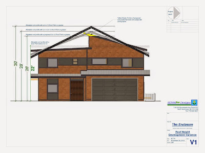
The work that Heather and Nathan have been doing at Tacoma Engineers has been first rate, and we are nearing the end of this challenging design. I have been so happy with my selection and waiting until I found the right match for this project. Much of the difficulty lies in my inexperience with structural design and building design in general, and the fact that I am both designing and drawing up my own house plans for the first time. I have taken blueprint reading and design courses in the past, but there was still SO much I did not know. Tacoma has been great at coaxing a more professional looking drawing package out of me (which I will post soon).
I also appreciate the patience shown by Tacoma as I aim for a dwelling with limited thermal bridging. Turns out limiting thermal bridging and structural requirements do not play well with one another and this has been trying for all involved. What has been a pleasant surprise is that my ‘gut-thumb-in-the-air’ engineering has been very close to acceptable. I personally designed most of the floor truss and beam layout and Tacoma has only needed to size the beams that I proposed. There have been a few extra beams required in the design, but nothing significant.
Contrary to the demands of the first engineer I hired in March, I actually do have a predominately 2x4 house structure (my taller gable walls had to be converted to 2x6 as did some interior bearing walls). This was important to reduce cost (a 2x4 is about 60% of the cost of a 2x6), reduce the embodied energy of the dwelling by building in less overall material, and most importantly - would allow me to utilize the salvaged 2x4’s from the house we will tear down. The used studs will not be tall enough for full height wall studs in the new structure (I have taller ceilings – 9ft first floor and 8.5 for the second floor), but they will probably meet 100% of the need for less than stud height lengths used as jacks, cripples, and general blocking. This will significantly reduce my costs and divert a very large volume of materials away from the landfill. The drawbacks with 2x4 framing is that you require 16” O.C. (may have needed some of this even with 2x6 construction based on loads), and a 2x4 stud has a lot less resistance to wind loading and therefore you require a larger volume of king studs around openings. I am currently working with Tacoma to reduce this (possibly with the use of stronger – engineered wood posts).
Drawing up both the architectural as well as structural plans (Thank-you Tacoma for allowing me to do the structural plans and save some additional costs) has been a monumental task I was prepared for on some levels but not fully expecting. Not counting the deign work done over the previous 2-3 years, I have put over a 1000 hours into the design, 3D model and 2D Drawings since July of this year. I have basically been working 15+ hours a day, 7 days a week, for the last three months. Things finally settled down this last weekend when I drafted the final structural drawing for Tacoma and now only need to process drawing mark-ups and revisions.
As we were close to being finished, I contacted the District for my pre-permit review of my plans and documentation. I was assigned an appointment time of 11:00 AM on November 27. Heather at Tacoma stepped up yet again and even came in on Sunday to work through the mark-ups on two of the more significant drawings. I was so grateful! Well the meeting was two days ago, and because I really did not know what to expect, I was both encouraged and disappointed all at once. The first few minutes went well although I could tell that the District staff were not overly impressed with the details missing from some of my architectural drawings.
But then I blurted out that I was not in compliance with the zoning bylaw and would be applying for a zoning variance. You see, I have planned since pretty much last fall’s design iteration, that I would be applying for a variance on the requirement to make the upper floor only 75% or smaller of the size of the lower floor. I was going to ask for permission to make my lower floor smaller than allowed to ensure I had a more compact envelope (limiting exterior wall surface limits your heat loss), to allow me to more easily comply with the new code required seismic braced wall panel rules (and the need for additional internal braced wall bands when you have the setbacks needed for a smaller upper floor), and most importantly, to allow me to design the house around our 4 magnificent 125ft+ mature cedars that hem in the south and west sides of our build lot.
At first the tone was feeling like, that would be too bad and I would be expected to take the trees down to make room for a larger first floor. I was told that the Zoning Variance Board was particularly steadfast against any form of variances at the present time, and that my application would probably be refused. As you can imagine, this was fairly distressing, and due to a family member’s pet emergency the night before, the 4 hours of sleep I had that night did not prepare me well for this enlightenment. One good idea that was raised during that part of the conversation as a possible plan B, was to build a 300 sq. ft. veranda on the back of the house which would bring me into compliance with the first floor size requirement needed to meet the ratio. This will probably be what I will do if my variance request is denied.
Then the real shocker kicked in as we continued to check the plans, my overall roof height was too high! On the surface it looked like both my north and south upper roof ridges were too high. As I had worked a month on these roofs to make them work with the thickness needed for structure and the insulation levels planned, and to ensure enough room for the smallest height windows Cascadia make in an operable lite for the Clerestory, this was very upsetting and for a while I just did not want to accept it. I had met with District staff in March and thought I had a clear understanding of the bylaw rules, but obviously I did not. Now things were looking very grim as to any chance of approval by the Zoning Variance Board. The staff member I was meeting with brought in others into the conversation, including some from the planning department. They discussed possible options that may be available to me. They agreed that as far as my floor ratio violation, my design met the intent of the bylaw (which is to promote interesting – non box architecture) even though it did not meet its technical specifics. I also had the impression they felt the roof infraction was fairly minor in nature.
This below PDF shows in yellow the portion of my roof assembly that is not in compliance with the bylaw. The other hatched lines show the larger massed roof I would be allowed to build if I went to a steeper pitch. Fortunately, when I got back home and measured, only the steeper north roof was not fully in compliance with the bylaw.
I was thoroughly deflated by this point until a suggestion was made to go for a Development Variance instead of a Zoning variance. Development variance decisions are made by the elected Council, and the Councillors have greater leeway to grant exceptions in the light of special site conditions or design goals. The application states "Development variance permits are normally considered where specific site characteristics or other unique circumstances do not permit strict compliance with the existing regulations." This was sounding promising and I got the feeling that the staff felt my chances of success with this process would be pretty good with a comment from the planning staff that they would have no concerns passing the application to Council for their approval. SO, it seemed that I was already through the first gate. Things were looking up.
The final checks focused on the existing shed we have at the back of our property. It is larger than allowed by the zoning bylaw and also a bit to close to two of the property lines. In the spring, I was counselled by staff to confirm this on the plans as an existing accessory building that was not being changed in any way and that it would probably be fine. The staff went away to discuss this and when my reviewer came back, she advised that I should include this in the variance request to 'legitimize' the existence of the building and that if for some reason, I did not go for variance or my overall variance was denied, they would figure out another method to allow it to stay in place. I have maintained it over the years and I was going to use it to build a plane with my neighbour a few years back. I then was going to use it as a very small wood shop but now that I will be building a full sized wood shop into the basement of the new house, I will probably just use this shed as a garden shed to store my law tractor and other yard tools and garden equipment. It used to be heated with a gas boiler, but this was recently decommissioned.
I left the, close to two hour, meeting yesterday feeling a bit beat up but at least optimistic.
I spent yesterday morning updating details on the drawings of concern to the staff and emailed that over to her. I then received the Bylaw Compliance Checklist back from her late afternoon on the same day identifying the 4 items I need to get a variance for. I spent yesterday afternoon and evening drawing up the PDF shown below and drafting a letter I will send to the neighbours, once again asking for their support. All 8 neighbours that are adjacent to the front and back of my property will be sent an official survey by the District and asked to indicate their support or opposition to my requested variances. I have been encouraged to contact them in advance to explain the rationale behind the variance requests and ask for as many letters of support as possible. I will distribute my info letter to them this weekend and will aim at applying for my variance on or before Dec 13 so that I have the best chance of being able to present my case to Council at their February meeting.
I was told that staff could possibly look at starting to process my building permit application in advance of the Council approval on the assumption that it would be approved. I was also told that I could apply for the demolition permit at any time and it was recommended I do this about 4 weeks before I wanted the services disconnected. This was very good news that gives me a good chance of not only being able to stay on schedule, but possibly even being able to start earlier than planned. As we plan to move out March 1, we could have the service cut anytime after that and start the dismantling of the existing structure during March instead of after the planned April 8.
Next few weeks/months will be exciting as I finish off with Tacoma and prepare the full drawing package for submission with my variance application. I will then need to move on to the plumbing, electrical, and most important HVAC design. These are all a separate permit process and therefore a different time requirements. The plumbing will be the first permit application needed right after the building permit (the drains need to go under the footings) and then the electrical application would follow my rough-in construction inspection. Then would come the HVAC. At this point, I do not plan to connect gas to the house which will save us connection fees, permit fees, and monthly utility connection fees. This may change after the HVAC design, but at this point I hope to utilize an air source to water heat pump for both my space and domestic water heating needs.
Well, now you are all caught up.
Wish me well and thanks for reading!

Sunday, 3 November 2013
Thermal Bridging and Dew Points
Anyone who has heard me speak for more than 10 minutes has
probably heard me talking about dew-point potential. It is at the heart of good building science
principles. Move the dew-point to
somewhere outside of your assemblies, and your assemblies will have a built-in
safety regardless of any air movement through them.
But for many, this dew-point conversation is esoteric and
abstract, they can not usually visualize a dew-point occurring (that they are
aware of, the condensation on the outside of a glass or can of cold liquid is a
demonstration of dew-points) and so cannot appreciate the importance of
reducing its potential in building enclosure construction.
Well by happenstance, I had an excellent example present
itself to me at my home this afternoon.
I was coming back from my neighbour’s house after ‘supervising’ the
dismantling of some scaffolding, when I observed condensation on the inside of
the window near my front door. Now, I
generally have single pane heavy aluminum frame windows throughout my home, so
condensation around the frame margins of the windows is not an unusual occurrence. However this window had a wood frame (site
built) and did not usually suffer from condensation.
Why the difference?
Insulation and air films!
 |
| Condensation spotted on the inside of the window. |
 |
| Inside of window is condensation free except behind some mail propped up against window. |
 |
| Condensation is definitely on the inside face of the window. |
 |
| General window surface temperature 56.5° F |
 | |
| Surface temperature drops to below 51°F behind the mail. |
 | |
| Temperature in nearby region is 68.1°F |
 |
| Temperature behind mail 56.4°F with an RH of 64% |
So, what does this all mean?
I have to admit, that this took a lot longer than it should
have to figure out. On the first round
of measuring, I had RH levels well below 50% and temps of 66.3°F ‘near’ the window
(my office is at 44% and 72°F on the other side of the house and benefiting from
all the heat being pumped out from the computer equipment). At these windows temps
and RH, the dew-point should have been around 47°F which was clearly well below my initial recorded window surface temp of 53°F behind the mail.
So why the condensation?
It then occurred to me that this was a delicate microclimate
and by removing the mail for too long to do the testing and photos, I had inadvertently changed the local
conditions and disturbed the air film that would have been against the surface
of the window. So, I put the mail back
to let the conditions come to equilibrium again and reran the measurements to
get the figures in the photos above. As
you can see, the temperature within a couple of ‘ft’ to the window was now over
68F and the humidity that was building up behind the mail was over 64%. This works out to a dew-point around 56°F and
with a window surface temp of just under 51°F, I was well below the dew-point and had condensation.
The mail was creating enough of a barrier to heat loss (acting as insulation), that it was lowering window surface temperatures over 5F and at the same time was creating
a micro-climate where the humidity was ‘trapped’ by still air and building up
well above the rest of the house.
This demonstration
highlights how delicate the balance can actually be and why heat-bridging in
assemblies is so critical. Whenever you
have isolated conditions that allow a small area of your assembly to cool in
relation to the assembly as a whole, or that allow the build-up of humidity,
you have the recipe for liquid water
formation and when hidden inside an assembly, that can and often does lead to disaster!
Subscribe to:
Posts (Atom)