Showing posts with label energy efficient. Show all posts

Wednesday, 15 October 2014

Does PassiveHaus make sense?

Just a short update to showcase an article at Green Building Adviser that perfectly sums up the conclusions I made about the Passive House program and why I cancelled my plans to build to that standard.

The author of the article, found at www.greenbuildingadvisor.com/blogs/dept/musings/it-s-not-about-space-heating, tracked the actual energy use of several homes in Massachusetts and has determined that even a modest investment in insulation and air tightness (termed a pretty good house by Joe Lstiburek) is more than enough to reduce the heating and cooling loads to the point where it makes more sense to concentrate on plug and domestic hot water loads as is shown in the below graphic.


Extracted from http://www.greenbuildingadvisor.com/sites/default/files/images/Rosenbaum%20-%20Graph%20of%20Eliakims%20Way%20data%20copy.preview.jpg

The real world data monitoring has also shown that the assumptions made in the PHPP (the modelling system for PassiveHaus) are often wrong.  The author states, “PHPP assumes 6.6 gallons [25 liters] of hot water a day per person, but that’s not enough for normal Americans.”

I jumped on board the PassiveHaus train for about a year in the early design stages of my upcoming build.  It was easy to be swept up in the well polished program and fall in love with the projected savings.  But as I became better and better educated on building science, source energy, and embodied energy, I felt their were huge holes in the program.  The underlying principles of air tightness and thermal bridge free construction were sound, but in my view the chase for heating and cooling reductions bypassed the sweet spot where it made much more sense, from an embodied energy and a cost point of view, to look at on site production than further reduction. The biggest stumbling block was the claimed 10-15% added build cost to reach PH when in reality it is much closer to 200% on average when comparing to a code min house (which after all is what the majority of homes in North America are built to).

In the end I decided to build a "pretty good house" and will monitor energy loads once occupied and then model whether or not I reached the sweet spot between reduction and production.

Thanks for visiting.  For the current status of the build please visit http://www.theenclosure.ca/project-journal/

PS: For an excellent article on why  more insulation is not always better, read http://www.greenbuildingadvisor.com/blogs/dept/building-science/diminishing-returns-adding-insulation

Friday, 28 March 2014

Variance Approved and Website Launched!

Wow, a lot has happened since my last update. 

For starters, we have moved.  You can read about the first few days of the move over on my journal at theEnclosure.ca It was a tiring and stressful time that I am very happy is behind me. Of course this was followed up by a week of sickness and a computer data loss that was the worst I have had ever experienced but fortunately I have been very lucky in this regard and so this was not crippling for me (just expensive - the whole affair cost over $1000 for data retrieval and the purchase of a second battery backup so both my Raid servers are protected).

The next piece of big news is that our Development Variance permit was approved last Monday night.  This was such a relieve after months of back and forth with the District.  They accepted my originally proposed upper to lower floor ratio of 87% (vs. the 75% required by the bylaw), but I had to redesign the roof so that I could lower it 12" and now only be 8" above the requirement of 26'.  This has resulted in the loss of my air barrier design utilizing a torch on membrane, so I will have to come up with a new game plan for creating a durable and effective air barrier at the ceiling location. Ideas anyone?

We have also been approved for our Construction Mortgage and I am thankful for the hard work put in by Tetyana Thomas at the Royal Bank.  They have really stepped up compared to most banks that would not loan to an owner builder. The challenge will now be to get to the first draw.  They will not advance funds until the foundation is complete.  This will cost well over $100K to get to with all of the permit and engineering costs built into this phase. I am still not sure where this money will all come from and we are going to need to do some MacGyving to get through this stage.  The ironic part is that they are then willing to advance 40% of the land value at the first draw which is ALL of the funds I will need to finish the project.  The appraised value for the finished structure is over $2M in today's market and they felt I should be spending over $800K to build.  I expect to spend less than half this due to my own sweat equity, salvaged materials, sponsorship, and a lower importance that both my wife and I share towards the 'lipstick' of a house.

Yesterday, I also received the final sealed drawings from the Structural Engineer and the GeoTech report.  This is the last part of the puzzle needed to apply for the Building Permit which I will do next week. Unfortunately the first appointment available was Thursday as I will be at a THERM training course all day Monday and Tuesday.

The gas/storm/sani/water services should all be disconnected next week and I will have Hydro swing the electrical service over to the new temp pole as soon as I finish installing it and call for inspection.  I hope to get this done this weekend.

But the greatest achievement was the launch of the project's website theEnclosure.ca I cannot thank Honeycomb Creative enough for their work on this site.  It is first rate just like all of the other work they have done for me.  I invite you to stop by and browse through the information that is available including a full copy of the plans, building assembly descriptions, and lets not forget the 'live' (actually snapshots updating every 3-5 seconds) video of the build site.

As I get caught up, I will post more information on the Varriance process for those that may need to go through a similar process.

As always, thanks for stopping by!


Thursday, 27 February 2014

Pacific Northwest National Labratory develops a new Algae fuel ready in about an hour.

Diesel created by algae has been on the radar for a few years now but is still only available in low volume pilot plants and is heavily subsidized.  Once of the largest stumbling blocks has been the energy needed to create the dry algae used by the previous processes.

PNNL has created a process that can work with wet algae (80% water) saving vast amounts of energy and time.  Their new process creates usable crude in as little as one hour.  The process also allows for usable gas to be extracted from the waste water stream increasing the efficiency of the process even further.

This is a large step in the right direction in getting the process closer to the efficiency and scalability needed to compete with the fossil fuel market.

You can read more about this innovative process here.

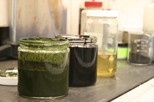
The process starts with whole green algae slurry with water contents between 80% and 90% (Photo extracted from PNNL)
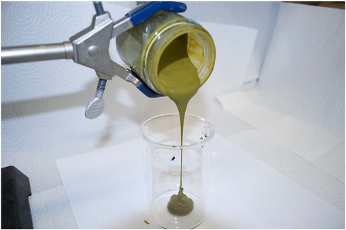
Under high pressure and temperatures that mimic the conditions found deep in the earths crust, the slime is converted into a light crude that can be refined in a traditional manner into gasoline, diesel and jet fuel. (Photo extracted from PNNL)


Sunday, 26 January 2014

Updated - Plumbing Design Complete - Not for the impatient!

Click here to view Completed 3D Plumbing Design - Updated

I plan on installing my own plumbing system in this house and am quite comfortable working with pipe.  However it had been several years since I had reviewed the plumbing codes and my memory from those days indicates there were a lot of rules regarding the sizing and routing of pipes!  So instead of talking the time to read and re-learn the code, I decided to contract out this part of the design.  I contacted an instructor of a BCIT 'Build your own house' course I had taken a few years back who provided the contact info for his son, a licensed plumber.


Richard Pugh  www.rpplumbing.ca 604-351-9145  Richard.pugh@rpplumbing.ca

I sent Richard off a set of preliminary drawings and asked if he could provide a plumbing isometric.  Now anyone who knows the plumbing business will understand that this is a strange request for a plumber and I was met with the expected hesitation.  Most residential plumbers do not draw out the system they install, and instead just complete a very rough plan, after the framing is complete, to allow for material ordering.  They then 'flesh' out the system as they are on site installing it.

If the designer (specifically those responsible for structural) has not taken into account the plumbing system, the plumber is left with some creative ways to route the pipes - especially the horizontal offsets and horizontal branch drains. And in some cases, with some plumbers that follow poorer practices, structure is modified to make room for the plumbing, compromising the stability of the structure (this seems to be rampant in the home renovation industry). In this conversation, it is important to remember that plumbers work in the world of 90º, 45º, and 22.5º fittings and all lines have to slope to drain.  If you have ever laid out a plumbing system, these constraints become front and center quite quickly and dramatically effect the routing of the pipes.

After a week or so, I met with Richard and went over his drawing markups. They identified the line routings and sizes and included key information like max change in direction between a water closet and its vent (225º) as well as the max distance between a WC flange and its vent (3m).  Everything looked great during our meeting review and I set off back to the office to fully flesh this plan out in my mind.


I have been using a program called Home Designer Pro to model the house in 3D and also create the plan views.  Unfortunately, this program does not include the functionality to add in plumbing.  So my Google search turned up a program called Quick Plumb (http://www.quickplumb.com/).  It had a 30 day free trial and a by month subscription after that.  The program showed a lot of promise, so I downloaded and started to model the layout that Richard had provided.  The program while easy to use on the surface, did have considerable challenges and only perseverance and patience provided a completed 3D plumbing model (I will give a full review of Quick Plumb at a later time).

Very quickly while starting the 3D modeling, I was able to see that some of what Richard had provided was not going to work, and I realized how difficult it is for plumbers to visualize a dwelling when only provided standard 2D floor plans.  The architectural 2D plans often provided do not typically identify the structural details like floor beams.  It is also difficult to visualize the alignment of each floor without a lot of measuring or being given some form of 3D model.

I unfortunately had not completed the structure at the time I had Richard start on the project so could not give him the structural drawings showing final beam placements. And I had no easy way to provide the Home Designer Pro 3D model to others.  So we had beams in the way of branches and stacks going through cavities reserved for pocket doors and similar interferences.  The pipe layout as drawn was just not going to happen.

SO I utilized the sizing and 'rules' presented in Richard's markup and set out to alter the layout to fit my structure.  In the end, I had to drop three beams in the basement (my beams are generally flush so concealed within the floor cavities) and re-space some floor trusses.  Fortunately, these beams could be dropped into either wall assemblies below, or into rooms that I did not mind having lower ceilings (like bathroom and sauna shower room in basement).  I also had to dramatically reroute the plumbing venting as I just did not have enough space in the floor assemblies for the drains AND vents to pass over each other (my cavities are 11-7/8" deep).

Richard still has to check over the resultant design, but I believe it is quite close to what I will end up with.  A 3D 'spin' of the design is available on my YouTube channel http://youtu.be/2aElBPP5Ryo.

Update: Richard went through and essentially 'approved' the plan.  I have updated the 3D spin to show the model now that I have also added in the required clean-outs.  The model still contains a code error (it was just too difficult to edit in the program). Can you spot it?

The design meets the following considerations:
  •  Basement will drain to a sump and then 'pump up' to the building drain that gravity drains to the Municipal sewer (note this is not how it is drawn. The software does not have functionality that allows for a pump up)
  • Upper two floors to gravity drain to Municipal sewer. 
  • Upper floor grey water lines will pass through a heat recovery device before exiting the building.
  • Toilets will drain separately from the rest of the system to accommodate a future grey water heat recover system upgrade and possible grey water filtering system to allow it to be reused in toilets.
As always - thanks for reading and I look forward to any comments you may have.

Monday, 13 January 2014

How It's Made - Roxul Stone Wool Insulation

The popular 'How It's Made' TV series visits the ROXUL factory in this 5 minute video http://youtu.be/clN-wB8Vl_k

You may also be interested in this video of ROXUL's "Test The Best" demo presented at building stores across the country. http://youtu.be/7rbRYs0XEAM

Thursday, 19 December 2013

FPInnovations - Guide for Designing Energy-Efficient Building Enclosures

Whether you are designing single or multi-family dwellings, this Wood-Frame Multi-Unit Residential design guide  from FPInnovations is packed with valuable design information and the relevant science behind each design.

Sponsored in part by the Homeowner Protection Office and prepared by RDH Building Engineering, the 244 Page guide contains information on building energy efficient assemblies in various configurations including split insulation, double stud, mass timber, and wood frame infill.


While I chose to not build to any of these specific assemblies in my dwelling, my design still relies on the fundamental principles expressed and recommended in this guide.  I have also had the privilege of attending many of the lead author's (Graham Finch - RDH) building science courses and seminars over the last 3 years.  His knowledge and ability to disseminate the information in an understandable manner has helped me immensely in my ability to absorb and understand the key building science principles discussed throughout this guide, including the importance of assemblies that can perspire, as well as the importance and impact of reducing thermal bridging.

Whether building a code minimum house or going to the other extreme and building a Passive House, this guide has got something for you and should be part of your reference library.

I give it two thumps up!

Sunday, 3 November 2013

Thermal Bridging and Dew Points


Anyone who has heard me speak for more than 10 minutes has probably heard me talking about dew-point potential.  It is at the heart of good building science principles.  Move the dew-point to somewhere outside of your assemblies, and your assemblies will have a built-in safety regardless of any air movement through them.

But for many, this dew-point conversation is esoteric and abstract, they can not usually visualize a dew-point occurring (that they are aware of, the condensation on the outside of a glass or can of cold liquid is a demonstration of dew-points) and so cannot appreciate the importance of reducing its potential in building enclosure construction.

Well by happenstance, I had an excellent example present itself to me at my home this afternoon.  I was coming back from my neighbour’s house after ‘supervising’ the dismantling of some scaffolding, when I observed condensation on the inside of the window near my front door.  Now, I generally have single pane heavy aluminum frame windows throughout my home, so condensation around the frame margins of the windows is not an unusual occurrence.  However this window had a wood frame (site built) and did not usually suffer from condensation.

Why the difference?  Insulation and air films!

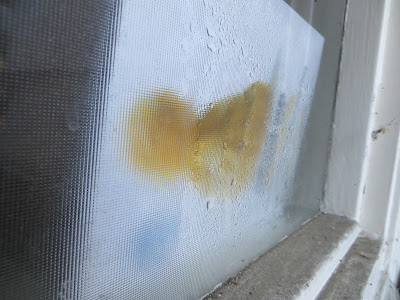
Condensation spotted on the inside of the window.

Inside of window is condensation free except behind some mail propped up against window.

Condensation is definitely on the inside face of the window.
General window surface temperature 56.5° F
Surface temperature drops to below 51°F behind the mail.

Temperature in nearby region is 68.1°F

Temperature behind mail 56.4°F with an RH of 64%

So, what does this all mean? 

I have to admit, that this took a lot longer than it should have to figure out.  On the first round of measuring, I had RH levels well below 50% and temps of 66.3°F ‘near’ the window (my office is at 44% and 72°F on the other side of the house and benefiting from all the heat being pumped out from the computer equipment). At these windows temps and RH, the dew-point should have been around 47°F which was clearly well below my initial recorded window surface temp of 53°F behind the mail. 
So why the condensation? 

It then occurred to me that this was a delicate microclimate and by removing the mail for too long to do the testing and photos,  I had inadvertently changed the local conditions and disturbed the air film that would have been against the surface of the window.  So, I put the mail back to let the conditions come to equilibrium again and reran the measurements to get the figures in the photos above.  As you can see, the temperature within a couple of ‘ft’ to the window was now over 68F and the humidity that was building up behind the mail was over 64%.  This works out to a dew-point around 56°F and with a window surface temp of just under 51°F, I was well below the dew-point and had condensation.

The mail was creating enough of a barrier to heat loss (acting as insulation), that it was lowering window surface temperatures over 5F and at the same time was creating a micro-climate where the humidity was ‘trapped’ by still air and building up well above the rest of the house.  

This demonstration highlights how delicate the balance can actually be and why heat-bridging in assemblies is so critical.  Whenever you have isolated conditions that allow a small area of your assembly to cool in relation to the assembly as a whole, or that allow the build-up of humidity, you have the recipe for  liquid water formation and when hidden inside an assembly, that can and often does lead to disaster!